Originally announced in 2010, the Crack is an affordable tube-based headphone amplifier kit offered by the Bottlehead Corporation located in Poulsbo, Washington State, USA. The company was created by the ‘President for Life’ Dan ‘Doc B’ Schmalle in the mid-1990s, and primarily offers DIY tube audio kits for both headphones and home stereos.
The Crack is Bottlehead’s biggest selling kit and has earned a reputation as a fun and easy-to-build project. Yet it yields an amplifier whose performance punches well about its price point. These are impressive results for an amplifier that Doc B originally stated: “was done partly as an exercise to see just how quickly and efficiently we could get a project from the hand waving phase to the production prototype phase.”

Bottlehead considers the Crack a simple circuit “Skill Level 1” kit. This makes it first-time builder friendly. It has a low parts count which keeps the price reasonable. It’s on its second revision (version 1.1) since release and can typically be completed in 5-10 hours depending on expertise and level of care.
One of the best things about a Bottlehead kit is the instruction manual. It is chock full of friendly hand-holding steps and pictures. It includes information on how to solder components for beginners and troubleshooting steps if things don’t go as planned. Coupled with the excellent community found on Bottlehead’s forums – where all questions you have will be (or already are) answered. – the support is outstanding. This takes a lot of the fear out of tackling a DIY product.
Tyll Hertsens, the former writer for Inner Fidelity, said
Building a Bottlehead Crack
Later on, I’ll caution you of some serious limitations of the design of the Crack, while hopefully conveying just how good this kit can sound (if paired properly!). But first, let’s take a look at building one. I’ve been through the process a few times, so I should have some tips and tricks you will find handy.
Please note that Bottlehead is rightfully protective of their intellectual property. The excellent and detailed instruction manual is what keeps a frugal DIYer from simply sourcing most of these readily available parts themselves (beyond a few kit specific parts such as the power transformer). The manual is available as a single time download upon purchase of a kit, and as such will not be shared here. I will try to walk the line between providing detailed information with good pictures, and not sharing too many specifics.
I’ve owned a version 1.0 Bottlehead Crack for a few years now. It sounds so good, that I’m happily limiting my headphone choices and I’m in no way looking to replace it. In this crazy hobby of upgrade-itis, that’s saying something significant.
I love DIY, and recently when a friend mentioned they were interested in the Crack, but lacking the skills and tools to build it, I happily volunteered. So what follows is tips from the building of their Crack version 1.1. Knowing it was going to be documented, and since it is for a friend, I completed it in a rather neater manner than my own.
Necessary Tools
Bottlehead’s Doc B recommends getting a decent digital multimeter (DMM) first. He says
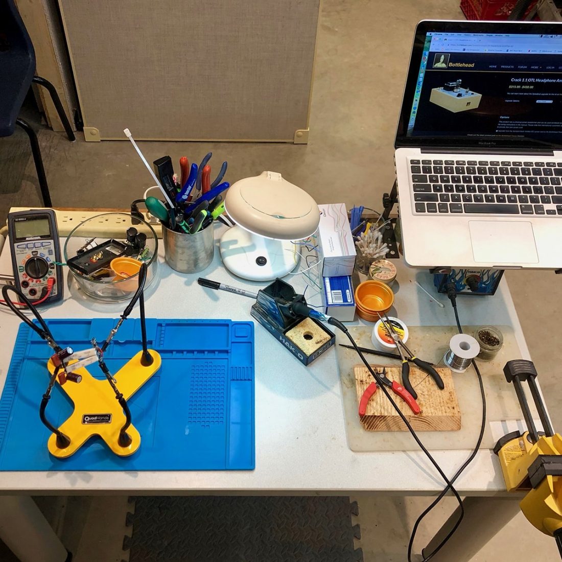
All total, depending on what you already own, you should budget an additional minimum of $100+ USD to buy:
- Digital multimeter (DMM) and alligator clip type leads is recommended
- Soldering iron (minimum 40 W)
- Rosin core solder (standard 60/40 or 63/37 tin/lead) intended for electronics
- Desoldering braid and/or solder sucker
- Needle nose pliers
- Small wire cutters
- Wire stripper (capable of stripping 22 AWG)
- Small Phillips screwdriver
- Carpentry or wood cabinet glue
- Wood stain, oil, or varnish
- Paint for chassis top plate
- Blue masking tape or picture frame type clamp
To be clear, you do not need any woodworking, electrical or soldering experience prior to building a Crack (although, of course, a little wouldn’t hurt).
The manual is very informative and you will actually learn many good practices and procedures by carefully abiding by what it tells you to do. Make no mistake, the voltages in a tube amp can be dangerous, but the instructions explain fully how to build and test safely.
Read carefully. Follow the instructions and warnings. Take your time. Double check everything as you go.
You don’t need to be an expert to tackle this project. Experience is the process of gaining knowledge or skill from doing. So, let’s get to doing!
Bottlehead does offer an assembly option for the Crack for $250. Clearly, this is intended to convince you to DIY.
Plan to Do the Finish Work First
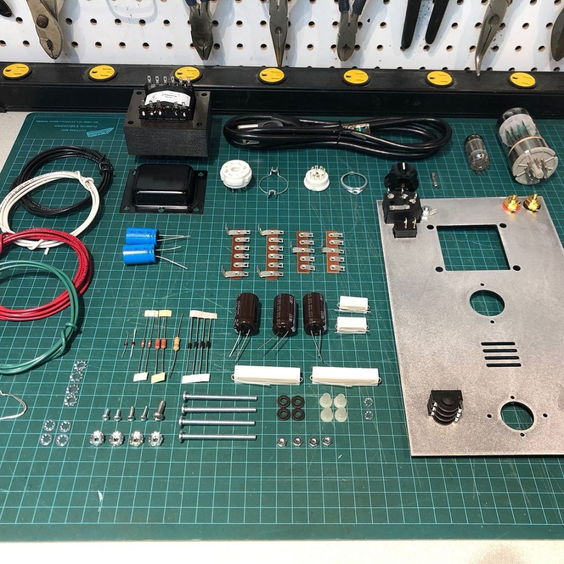
The kit is shipped completely unassembled, ensconced in packing peanuts in a small cardboard box. Inside you will find four perfectly cut, unfinished wooden boards and an unfinished metal plate with all the necessary cut-outs for the top.
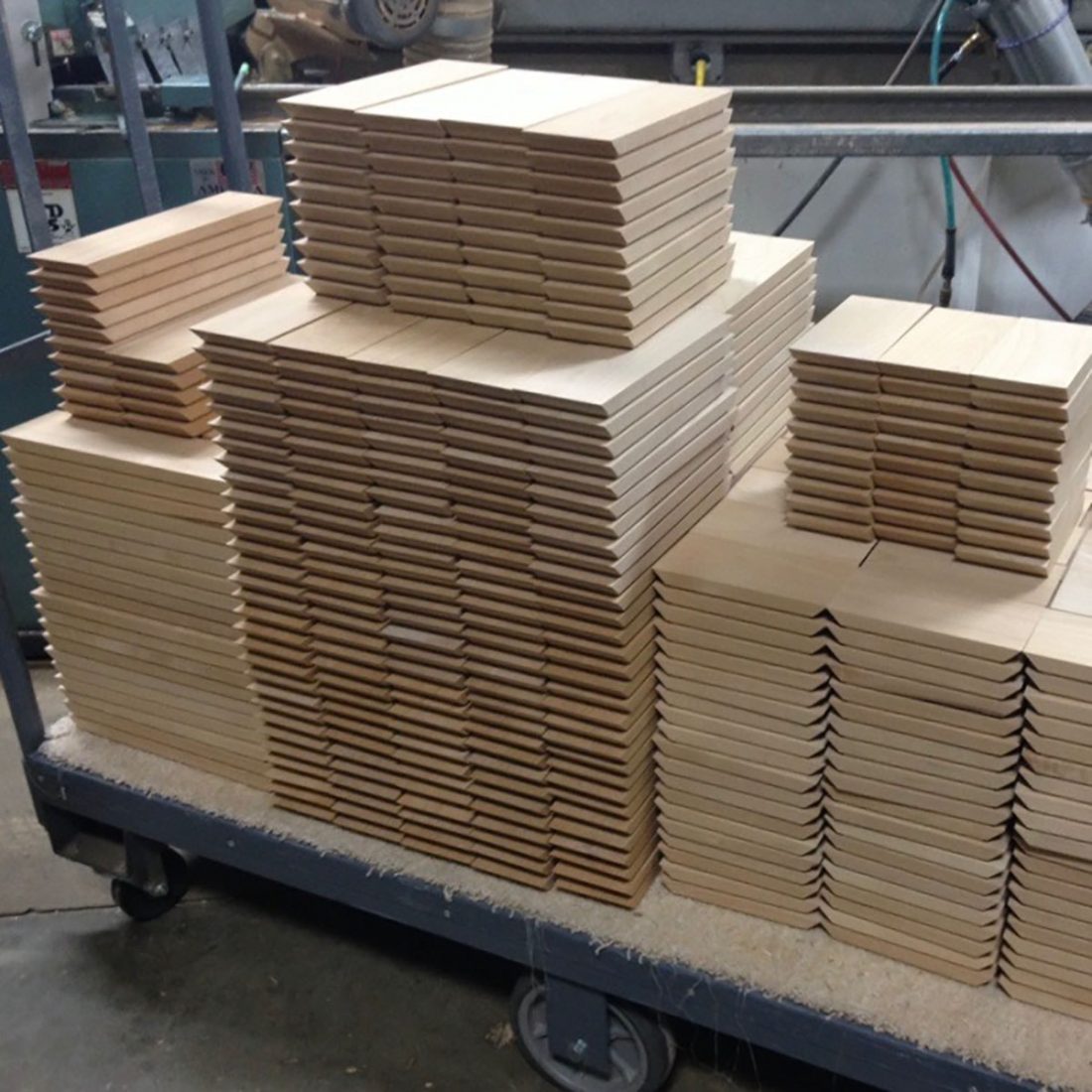
The wooden bases are made by a local woodworking shop that has been providing them for about 20 years. Being in the pacific northwest, alder is one of the few commercial hardwoods cut locally. The process of creating the wooden parts is complicated and extensive. It ensures a perfectly cut and finished end product.
Fight the urge to just launch right in and start assembly. It’s actually important that you have done your research first and have already decided on what you want the final product to look like. While you can leave the wood and plate unfinished, the best-looking result will come from properly finishing the surfaces FIRST.
Luckily it will take a few weeks for the kit to arrive after ordering it. This gives you plenty of time to google pictures, and decide what looks best to you. Does the retro design inspire thoughts of cream and teal antique automotive styling? Perhaps a dark stain and hammered metallic finish to enhance the steampunk sensibilities? Design it to best fit your tastes.
Top Plate and End Bell Finish
It’s up to you, but in my opinion, give the final look much consideration before you start, because you have to AT LEAST have the top plate and transformer end bell painted or powder coated before assembly begins. It isn’t possible to finish them later without taking it all apart.
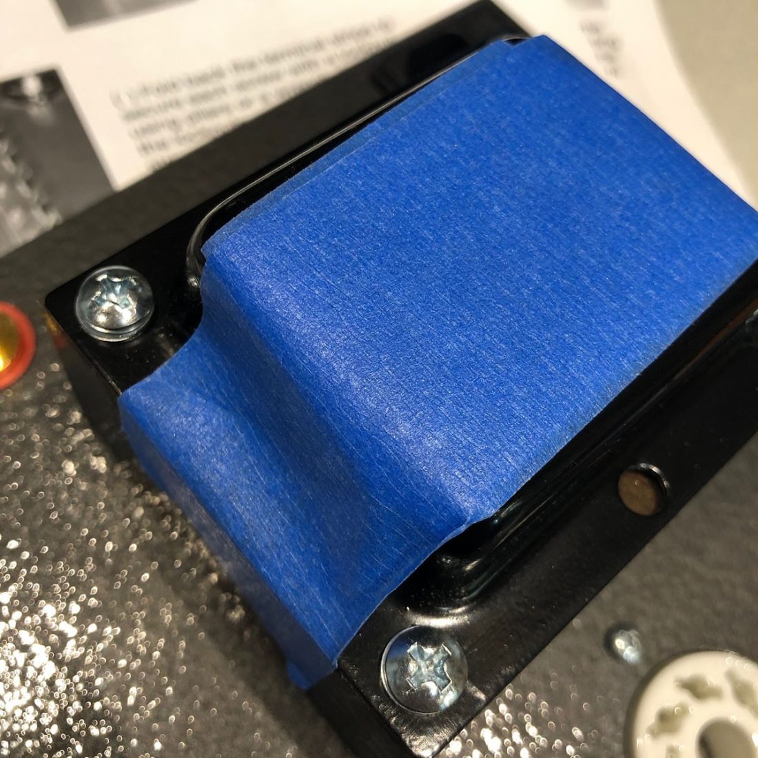
Clean the surface of the top aluminum chassis plate and steel end bell with soap and water or isopropyl (rubbing) alcohol. Ensure there is no residue left behind to interfere with the paint. The finish on the plate and bell is sufficient for adhesion, so no sanding is required. The manual states that the end bell will rust if not treated with paint or a clear coat.
Of note, you can sand the top plate with a random orbital sander and get an interesting brushed finish. I recommend sanding the bottom of the plate after painting to make sure it is clean and ready to act as a ground for the electronics.
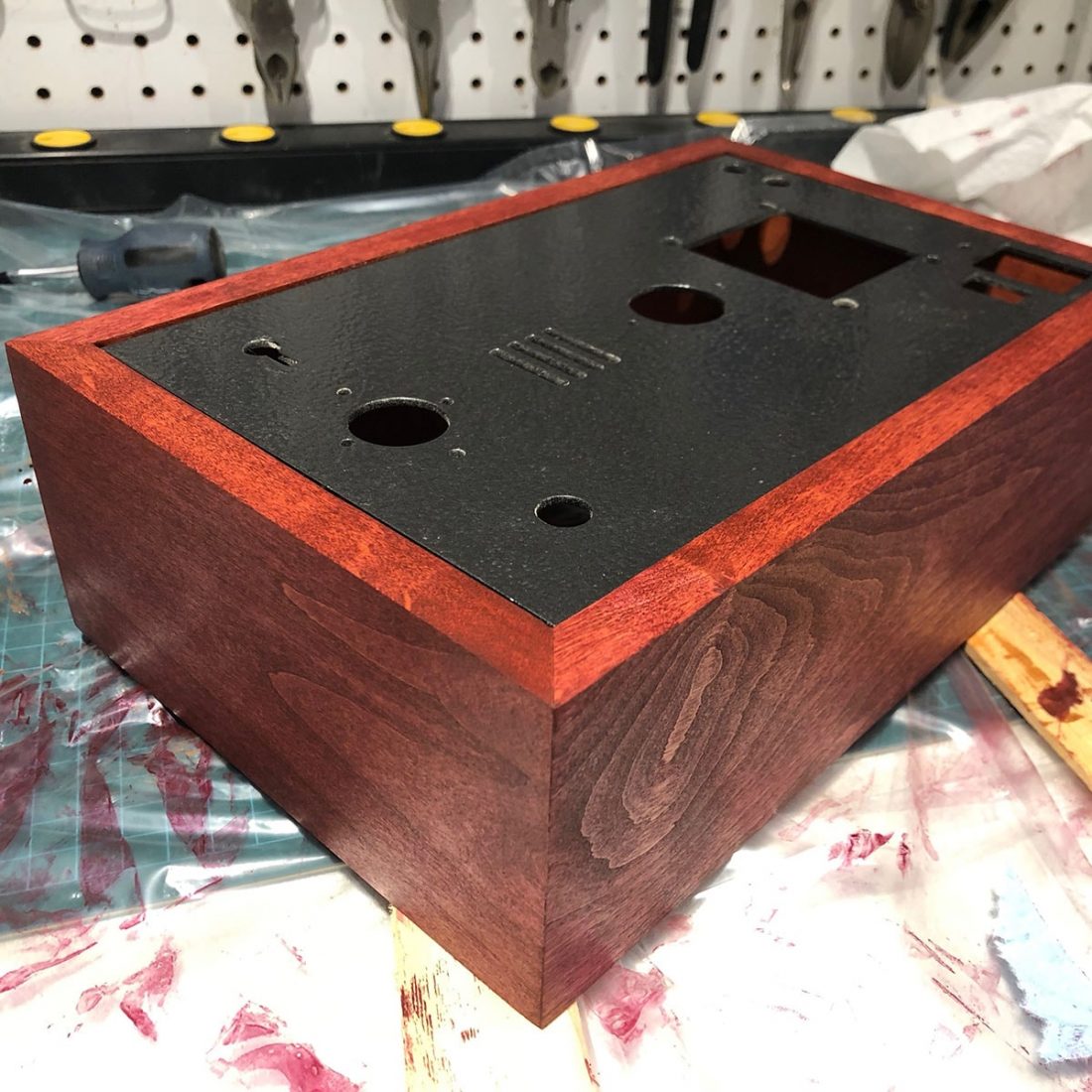
I’ve had great results using Rustoleum hammered finish spray paint for the top. Follow the directions on the can, but several light coats and at minimum several days (a week or two is better) of drying and hardening time pays off dividends. For the kit in the pictures, I had actually painted the top months before starting assembly. Clearly most folks will not want to wait that long, but as much patience as you can muster is recommended.
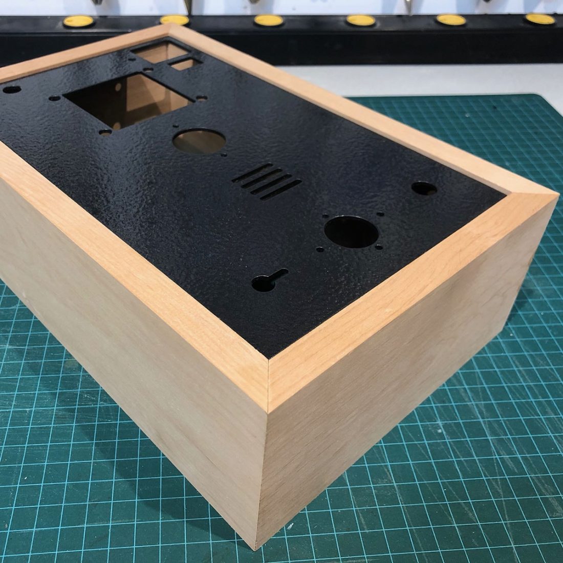
Wooden Case Assembly and Finish
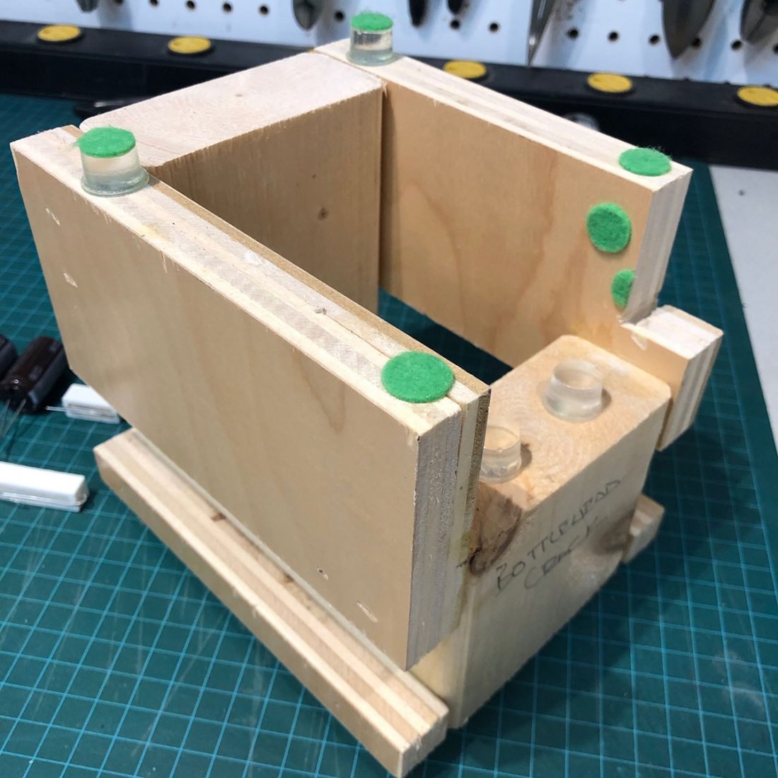
I recently had the chance to chat with the shop responsible for providing the wooden case parts for Bottlehead. I asked for their suggestions: “For gluing, I just use tape stretched tightly over the outside of the joints while the parts are laid flat and face up. Then flip them over and apply some wood glue to the inside, letting it soak in just a bit before folding it into a box and taping up the last joint. Do this on a flat surface and make sure that it sits as level as possible.
Once the glue is dry, I sand off any residue. A sheet of fine sandpaper laid flat (I contact cement it to a flat piece of scrap) works well. Plan on doing fine sanding cleanup to ease the sharp edges before any finish goes on. The outsides of the miter corners can be fully closed up by carefully rubbing them on a hard surface to slightly fold over the wood fibers.” You can’t get directions from anyone more qualified than that!
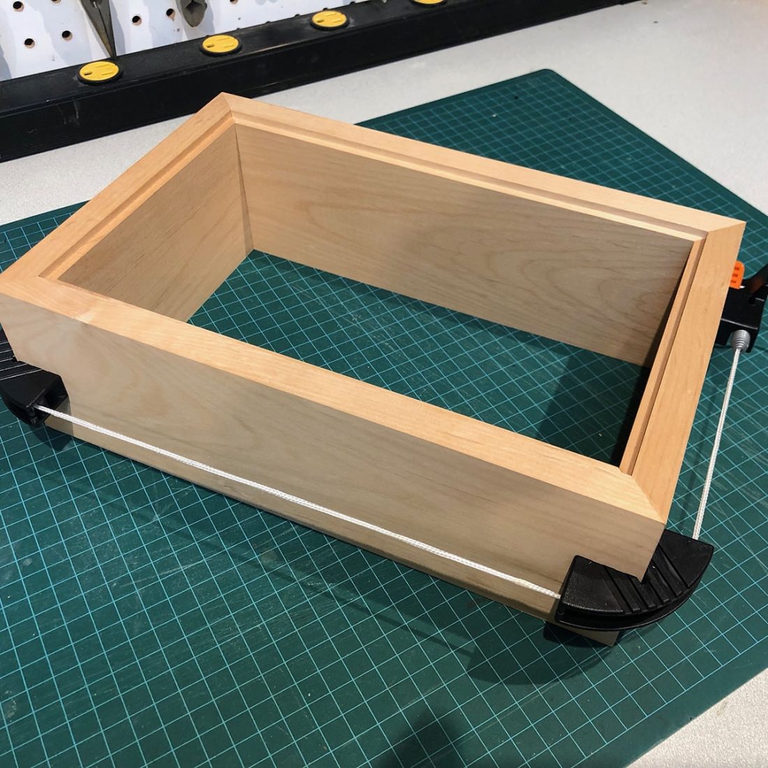
Assemble on a perfectly flat surface and align the corners PERFECTLY. There’s no excuse not to spend an extra few minutes to ensure things line up exactly. Allow to dry overnight (or as per the glue instructions) and make your final finish decision.
When sanding, move upwards through a few sandpaper grits and finish with a 220 grit (or there about – for example, 60-120-220 in that order). Be careful not to round off the corners and edges unless that’s the look you are going for.
On a theoretical future build, I plan on using a router to round the top outer edge, while leaving the other edges and corners sharp. I think this will yield a nice finished look.
It’s all personal preference. You could just oil the box with Tung oil or seal it with a clear coat and be done with it. Since you are stuck waiting for the paint to cure and dry fully, you might as well take your time and make the box as attractive as you can.
Of course, there’s no limit in picking an attractive paint or stain color (stain allows the grain of the wood to show through). If staining, I would recommend sealing with a Varathane semi-gloss or gloss after a few coats are allowed to dry. I’ve had great luck with rattle can spray Varathane on small projects like this.
As far as finishing, the shop recommends: “I don’t normally do finishing, but I think your process is the way to go. Small dents can usually be swollen back up with some warm water and resanded. Alder has complex grain structure that can get blotchy if you go straight to stain. A wash coat followed by very fine grit scuff sanding before adding any color is the usual method.”
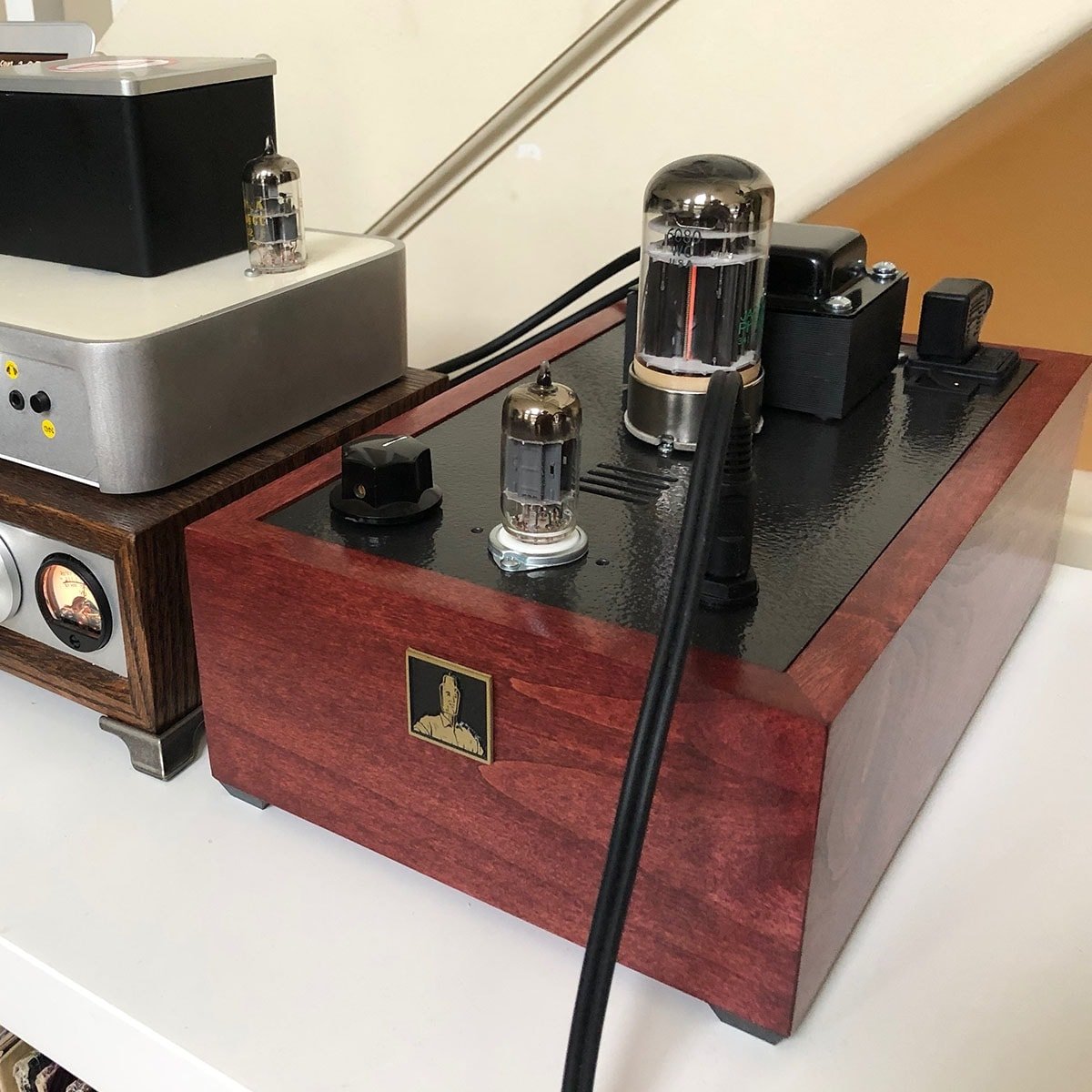
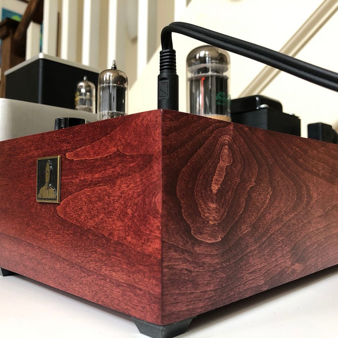
Badge and Feet
I suggest paying extra and ordering the $8 metal embossed Bottlehead badge. It is backed by adhesive and really finishes off the case once you’ve allowed it to dry. It definitely creates a more professional looking result.
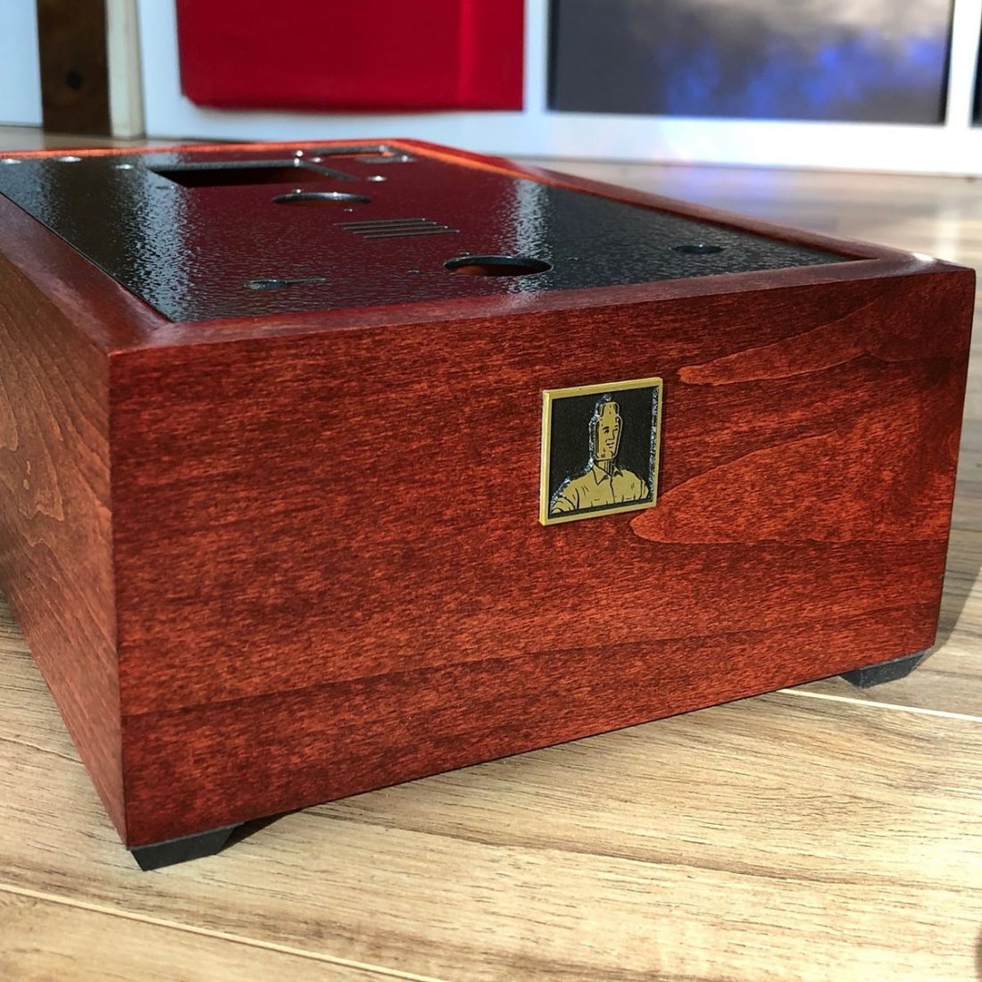
Included in the kit are 4 rubber feet that lift the case. Adding the feet are not optional. The kit relies on this gap around the bottom of the box (there is no bottom pate) for air to enter and to cool the hot components. Hot air exits through slots in the top plate. Failure to properly provide a gap will damage the Crack. I used pewter feet from Lee Valley Tools for my personal build.
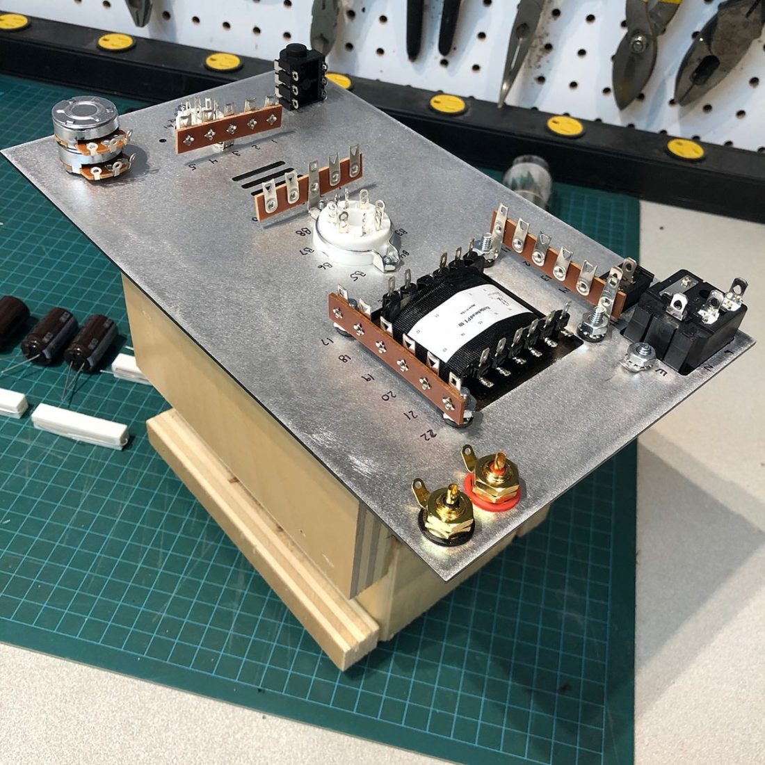
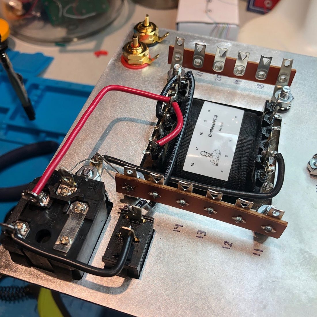
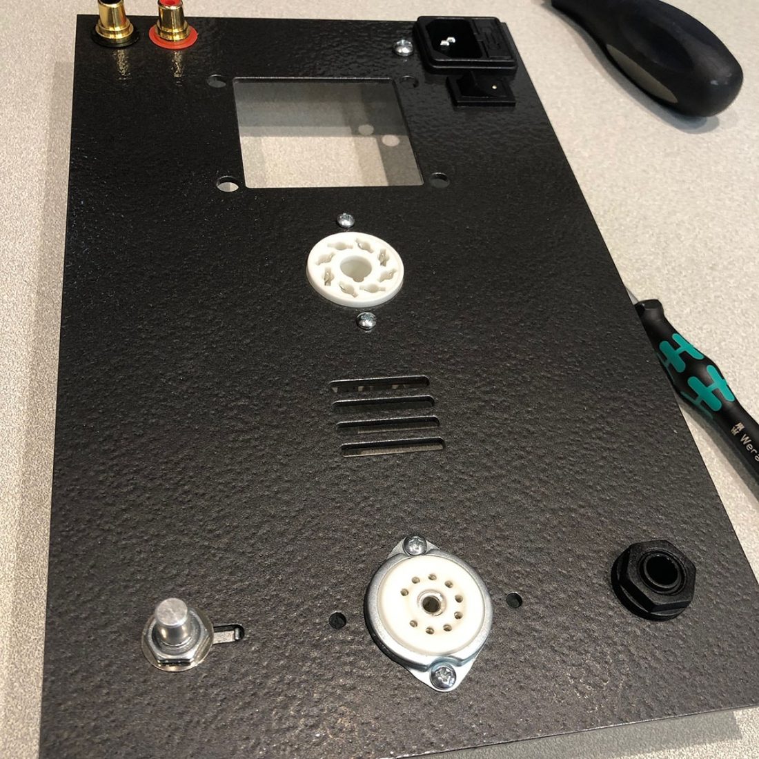
Building up the Chassis Top Plate
This section is where you (FINALLY) get to start attaching components to the top plate. Power outlet and switch push through from the top and click into position. RCA jacks, headphone socket, and volume control are threaded through the plate.
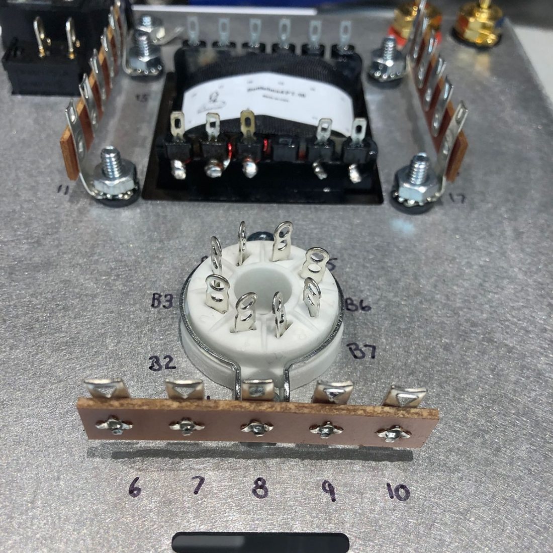
Screws and nuts are used to hold the ground point, terminal strips, tube sockets, and transformer securely to the chassis. Once all this hardware is attached, take the time to write the terminal numbers neatly onto the chassis. I used an ultra fine Sharpie marker. This helps immensely when assembling, as all instructions refer to running wires from terminal X (upper or lower) to terminal Y (1U-22L, etc).
Time to Turn On the Soldering Iron
Read the soldering tips page carefully. You might just learn something. Almost all the troubleshooting steps involve finding an improperly soldered connection. It’s so much easier to make sure they are all done right the first time.
An important note about the instructions that is easy to miss: “When the manual says “attach” that refers to wrapping the lead or wire around a terminal. Do not solder terminals until explicitly instructed to do so, as some terminals will be used by more than one component.”
I wish the instructions would highlight, color or bold the text when they switch between ATTACH and SOLDER. Even being careful, I sometimes soldered too early because I missed the “attach” in the sentence. Not a fatal mistake, but it does make it easier to do it in the right order.
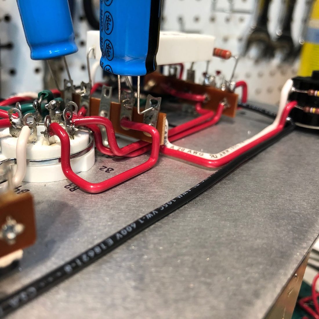
The solid core wire included in the version 1.1 kit is very forgiving and easy to strip and use. Also, not to worry, even though the instructions give specific lengths to cut each wire, there is extra included so you can be creative (as I was) with the wiring layout if you desire. I still had 6-10 inches extra of each wire color after completion.
The power transformer can be wired to properly match your mains voltage (under 115V, 115-130V, 210-225V, 225-235V, or 235-245V), making it universally compatible.
Tests are performed after wiring the power lines, after wiring the secondary transformer voltage, and when wiring the power to the tube sockets (glow test).
Solder Joints
There is a general troubleshooting section included at the end of the manual. While it focuses on a number of issues, the most common one is typically an improperly completed solder joint. The manual states that
There’s a lot more detail in the manual. You should read it!
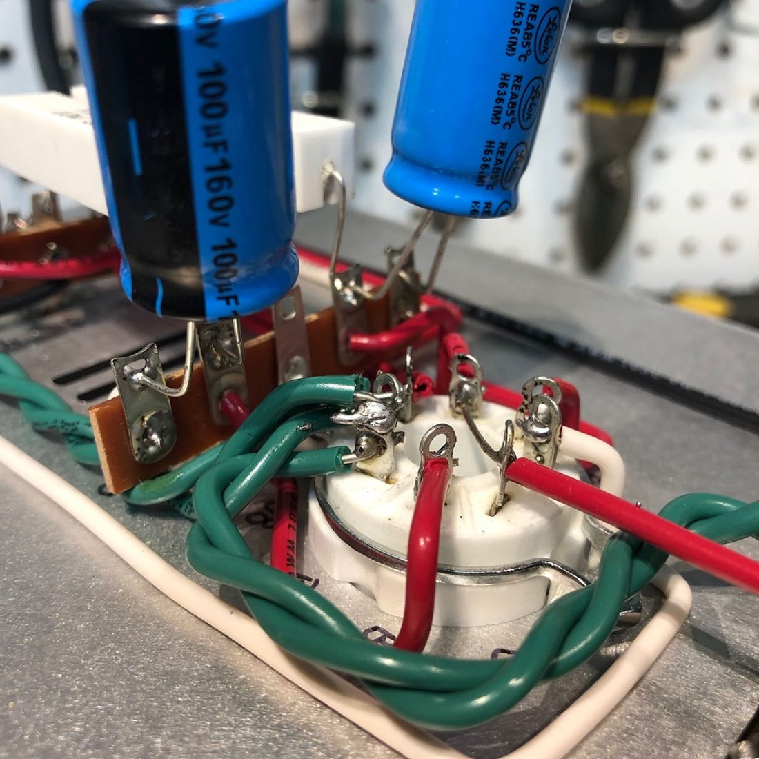
Input Wiring
RCA input wires are braided to resist noise (it doesn’t require shielded wire) and are attached to the volume potentiometer. From there to the small input tube socket and onwards to the headphone socket.
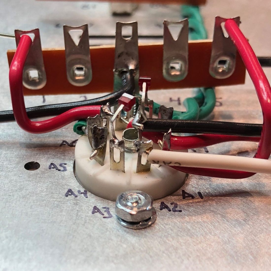
Bottlehead uses LEDs to set the bias for the input tube to 1.56 volts. The HLMP-6000 LED used is unfortunately fragile with very thin legs, but it has a low effective resistance and is electrically quiet, making it an excellent choice. Soldering the LED is the first tricky part of a basic Crack build. Ensure the correct orientation, cautiously curve the legs to allow for the flexing of the tube pin sockets when tubes are inserted and removed, and carefully solder in place.
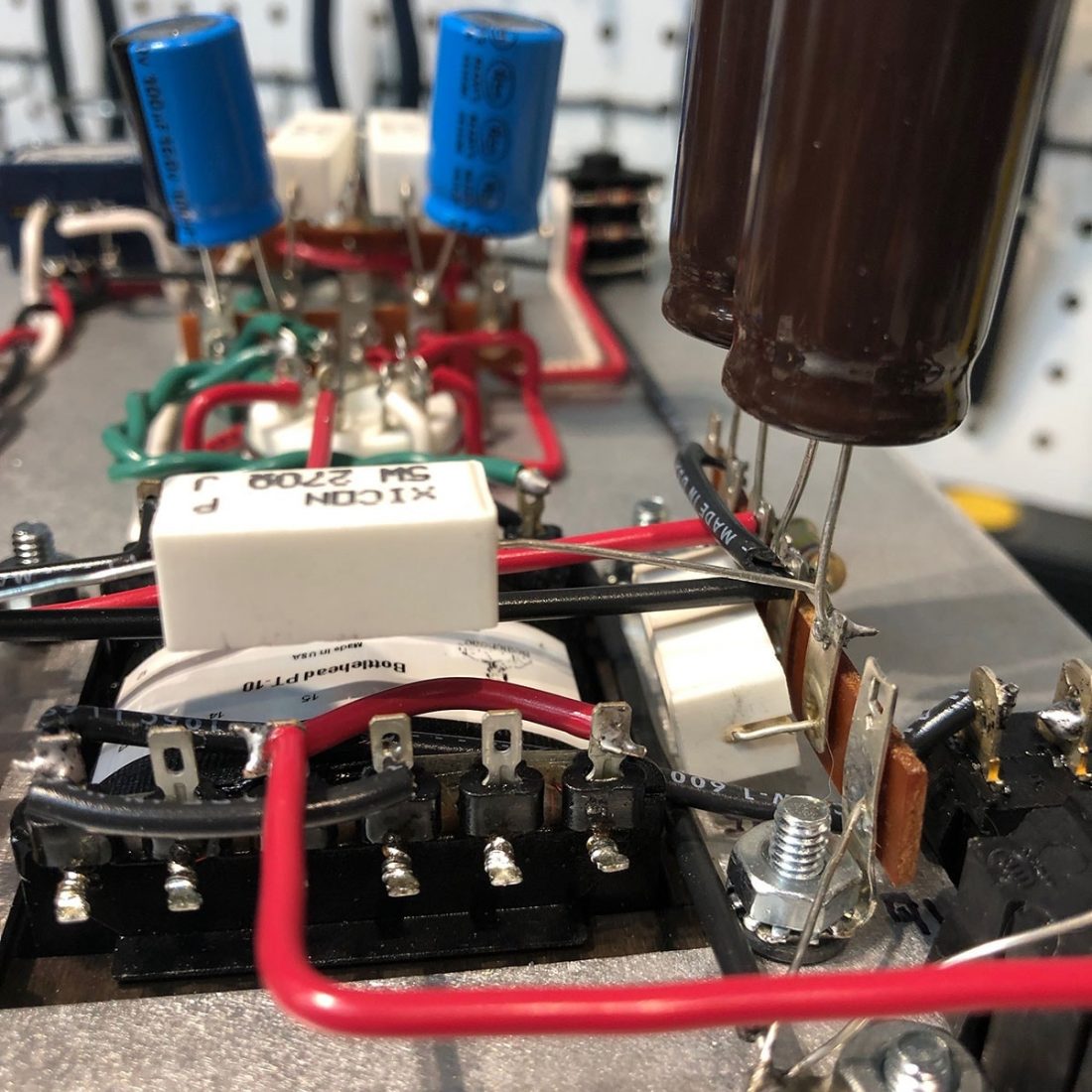
The Power Supply
Next up is the high voltage power supply. In my opinion, orienting and soldering the 4 diodes in the power supply is the least enjoyable and most fussy part of the build. Especially if you are trying to do it neatly with nicely squared off bends.
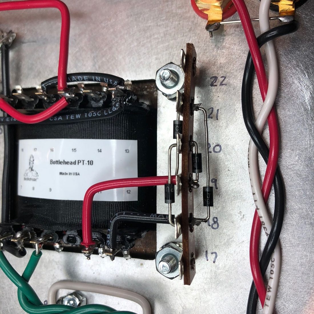
Note that wire lengths, component spacing, and component orientation matter and making a mistake here can irreparably damage the power transformer. An expensive ($100 + shipping) punishment for not being careful.
On the topic of neatness, I eyeball the appropriate length and use the needle nose pliers to bend 90-degree angles in the component leads wherever possible. It looks so much tidier, but it isn’t necessary to do so.
Remember that those rectangular sand block resistors in the kit are big and beefy because they get HOT. Ensure when you install them to give space around other components wherever possible.
A note about the capacitors and diodes in the kit. They must be installed with the correct polarity. Polarity is marked with bands physically on the component. Follow the directions carefully and triple check. Things will catastrophically fail if installed in the wrong orientation.
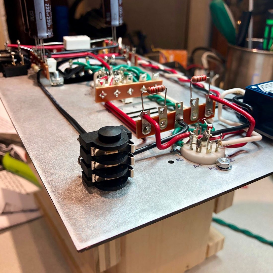
Output Wiring
This is the final stage of the basic Crack build. Add a couple more capacitors (note orientation!) and a couple of resistors on the headphone jack.
There is a simple fix if you find the Crack is too loud and you would prefer more usable range in the volume potentiometer (this also solves any channel imbalance at low volumes). Add a couple of 75K resistors (1/10 Watt or greater) where the red and white wires connect to the volume pot and a 33K resistor between each of the outer pair of lugs on each level of the volume pot and ground lugs on the pot.
Testing and Listening
That’s it. Soldering is done.
NOW DOUBLE CHECK ALL YOUR CONNECTIONS TO MAKE SURE YOU DIDN’T MISS ANYTHING! CHECK THOSE CAPACITORS AND DIODES AGAIN!
You will do a resistance check and if passed, a voltage check before plugging in a source and headphones. Once everything tests in the correct range, I recommend finding a pair of inexpensive (and sacrificial headphones) for the first listen. Better safe than sorry. If everything still goes well, grab your favorite high impedance headphones and give it a real listen.
If you run into any odd issues, check all your connections for the umpteenth time, follow the troubleshooting steps in the manual, or if all else fails, join those asking for help in the forums.
Why Doesn’t Everyone Own One?
In very many cases, the performance of a Crack is very favorably compared to amplifiers costing much more. It is almost universally hailed as the affordable end game option when paired with the timeless Sennheiser HD600 or HD650’s.
It offers top tier sound at a mid-tier price – especially with the release of the $200 Massdrop HD6XX (identical to the HD650 at a much lower price point).
A Controversial Design
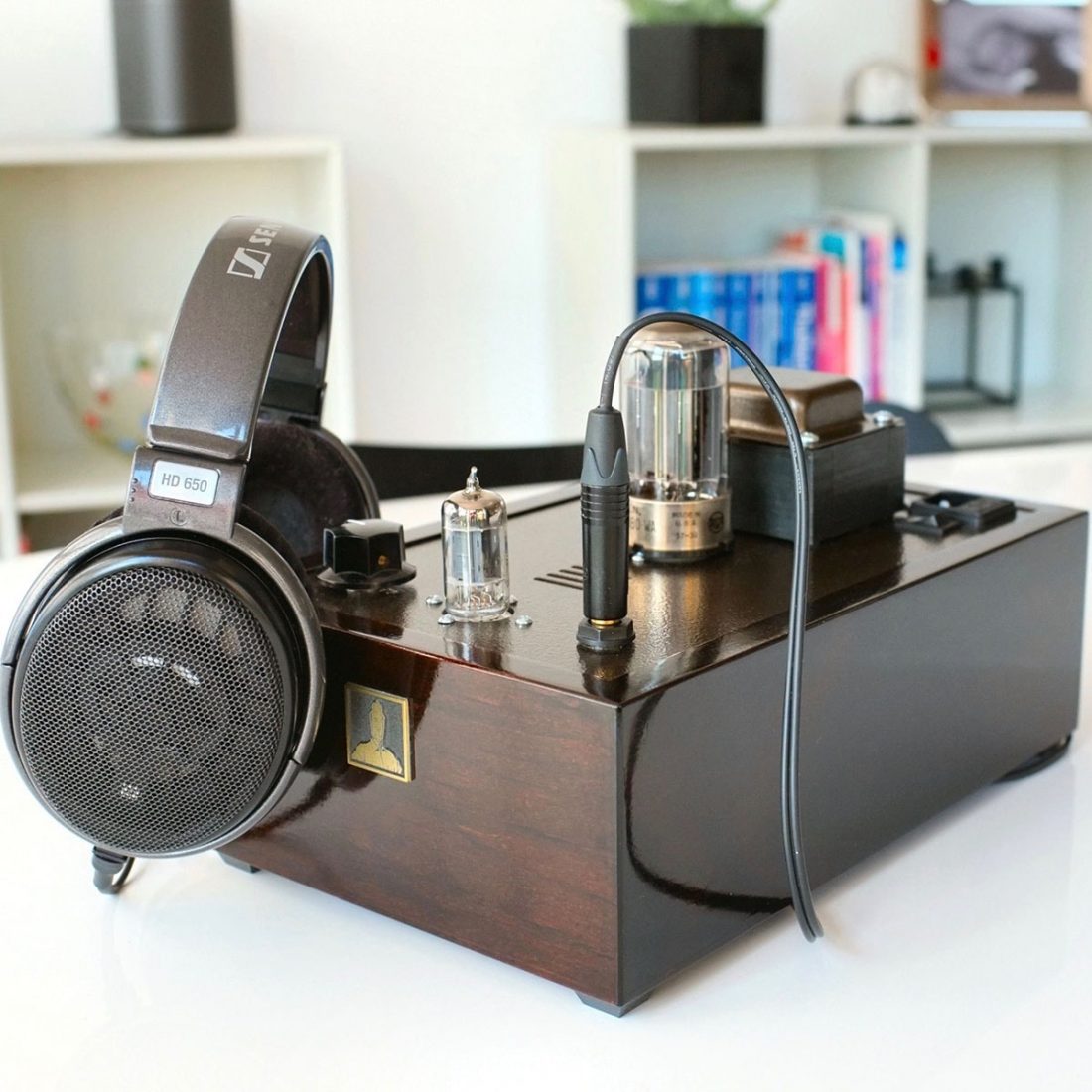
The design of the Crack delivers both its principal strengths and weaknesses. The Bottlehead aesthetic tends to be a polarizing one. Atypically, all components, controls and inputs/outputs are on the top plate which sits unattached on a plain wooden case. This simplifies the design, makes it easier to work on and lowers the price, but creates a retro-utilitarian look that you either embrace or not.
Aesthetics aside, the critical thing to understand about the Crack before purchasing, is that it is an OTL (Output-Transformer-Less) amplifier.
OTL Amplifiers
The OTL design seriously LIMITS the variety of headphones it is compatible with. Really there are only a few that will work and sound proper powered by a Crack. However, those that do, sound wonderful.
The Crack will not work well with most headphones. I want to make this absolutely clear. The Crack is extremely picky with headphone pairing.
The Crack has no output transformers and as a result of its particular design, it has a high output impedance (120 Ohm). Output transformers in tube amplifier designs are typically used to lower the amplifier’s output impedance and to make them more universally compatible with many headphones.
Benefits of OTL Amplifiers
Tube amplifiers with output transformers are typically preferred due to the flexibility of headphone pairing options for the owner, however the OTL design has a few significant benefits.
Output transformers are large, heavy, and difficult to manufacture. This results in significant cost savings if there are no output transformers in the design. Additionally, output transformers can be a major source of distortion, so higher sound quality can (theoretically) be achieved with a properly designed OTL amplifier.
OTL Amplifiers are Current Limited but High Voltage
While it can provide high voltage, the combination of the Crack’s high output impedance and the headphone impedance limits the amount of current it can provide. This creates a couple of compromises:
1. Will it work well with Fostex, HifiMan, Audeze planars?
No. The Crack is not suitable for planar headphones which require a lot of current. Look elsewhere for an amplifier if you own this type of headphone.
2. The Crack is only suited for high impedance headphones that require (or benefit from) a lot of voltage.
The rather unique specifications of Sennheiser and Beyerdynamic headphones are why they are frequently mentioned when discussing the Crack.
For instance, the Sennheiser HD6xx line can require high voltage (3-6V) at around 100Hz, making it a poor pairing for many lower powered mobile devices, but an ideal match for the Crack’s characteristics.
Low Impedance Headphones will Suffer from Distortion and Bass Rolloff
The combination of high output impedance and low headphone impedance limits the ability for clean sub-bass reproduction – even if the headphone is capable of it when paired with an amplifier with low output impedance.
Nwavguy (an anonymous engineer who created excellent and controversial DIY audio designs such as the O2 headphone amplifier) explained that “tube amps with no output transformers (like the Bottlehead Crack), for example, have much higher distortion into low impedance headphones.”
You can expect bass roll-off using headphones with an impedance lower than the recommended 200 Ohm minimum with the Crack.
With the Crack, the roll-off at 20Hz (lowest audible frequency) is only 0.2 dB for a 300 Ohm load (such as the Sennheiser HD650) – or in other terms, that combination produces the full range of audible sound with almost no roll-off.
However, if you use headphones with the same impedance as the Crack (120 Ohm) the roll-off will be approximately 1.5 dB at 20Hz. Using common 32 Ohm headphones, roll off is a likely audible 3 dB at (a higher) 50Hz.
Whew. Let’s just stick with high impedance headphones.
What Headphones Work Well with the Bottlehead Crack?
Typical recommended pairings include:
- Beyerdynamic DT880 (600 Ohm)
- Beyerdynamic DT990 (600 Ohm)
- Beyerdynamic T1 (600 Ohm)
- Sennheiser HD580 (300 Ohm) Note the new HD58X model is 150 Ohm.
- Sennheiser HD600 (300 Ohm)
- Sennheiser HD650/HD6XX (300 Ohm)
- Sennheiser HD800 (300 Ohm)
See what I mean about limited choices? That’s a grand total of 2 German headphone companies and 7 models of dynamic headphones.
The Sennheiser HD650 tends to be recommended as the superlative match. Perhaps the sound of the HD650 is best complimented by the Crack’s unique blend of tonal distortion and harmonics. The impedance of the HD650 tends to peak in the low bass region (remember that 100 Hz spike), so the high voltage Crack delivers a little extra oomph here.
Certainly, I found the dynamics and presence of the HD650 to come alive when paired with the Crack and, if we’re being honest, I found the HD650 a bit boring for my tastes powered by any solid-state amplifiers that I have tried.
There are a few other high impedance headphone choices out there (such as the Audio Technica ATH-R70X – 470 Ohm or the ZMF Atticus/Aeolus – 300 Ohm) but they don’t get much mention about pairing with a Bottlehead Crack. Higher cost models may simply be too expensive to be widely recommended for this relatively lower cost amplifier.
Of note, I own both the Sennheiser HD650 and Beyerdynamic T1 (version 1) and use them exclusively with my own Bottlehead Crack build.
Conclusion
Yes, the OTL design requires compromises. There are serious limitations. You must select the appropriate headphones to pair with the Crack. Building a kit requires planning and work to complete properly.
But damn. The Bottlehead Crack just sounds so good, I can happily live with limitations.
Next up in Bottlehead Crack ownership is a discussion of the multitude of modification and upgrade options. No headphone amplifier has been more tweaked, enhanced and dare I say ‘pimped out’ than the humble Crack.
In the “Upgrading the Bottlehead Crack Headphone Amplifier: A Comprehensive Guide” article, we will take a look at where improvement is recommended, where it is important, and where it can become just chasing diminishing returns.
Not one word about the importance of the “mechanical” attachment before soldering.
Fair point. Thanks for the suggestion. The intent was to push folks towards reading the manual where proper soldering etiquette is defined, by calling out that most issues are around improper joints. I’ll submit some edits that address this more clearly.
Thanks again.
Hi, what DAC do you recommend to use this amp with a PC?
Thanks,
Any DAC will do. Check out my recent Topping D10s or Soncoz DAC reviews for good options.
Thank you!
Hi, The 1990 250 is a good match? Thanks
I haven’t tried the 1990 (although I want to at some point!) but it should be a good fit for the Crack.