
oSo now you have assembled your stock Bottlehead Crack OTL amplifier. You could stop now and live in personal audio bliss. The Crack sounds so good, there really isn’t a NEED to try to improve it.
Or is there?
Clearly, you are a DIY type person. Very likely you enjoyed the build process and now are wondering ‘what’s next’? Damn it, you own a soldering iron for a reason!
The Crack is an affordable kit, so builders will inevitably want to tinker and further improve performance. Bottlehead supports creativity, but they strongly caution you to build and test the Crack in stock form first, before attempting any modifications.
Upgrades and Modifications
To start our discussion of worthwhile modifications for the Bottlehead Crack, let’s check in with the expert. The Bottlehead company was created by the ‘President for Life’ Dan ‘Doc B’ Schmalle in the mid-1990s and over the years, he has shared his wisdom of where to start with Crack modifications. Doc B states
Basic modifications can be broken down into a few categories:
- Bottlehead Speedball – Camille Cascode Constant Current Source (C4S)
- Tube Rolling
- Capacitors
- Volume Potentiometers (Attenuators)
- Other Modifications (not recommended by Doc B)
Speedball Upgrade
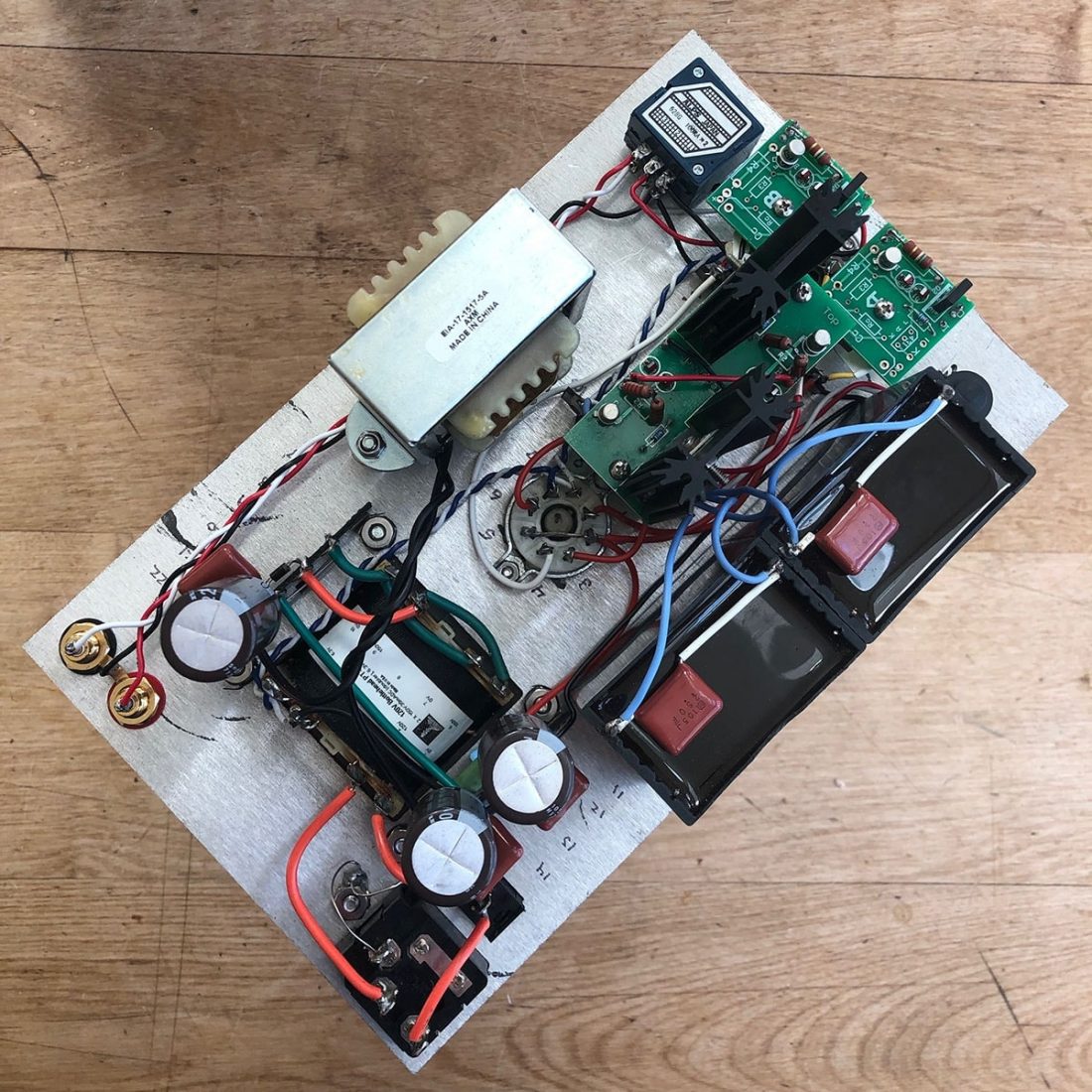
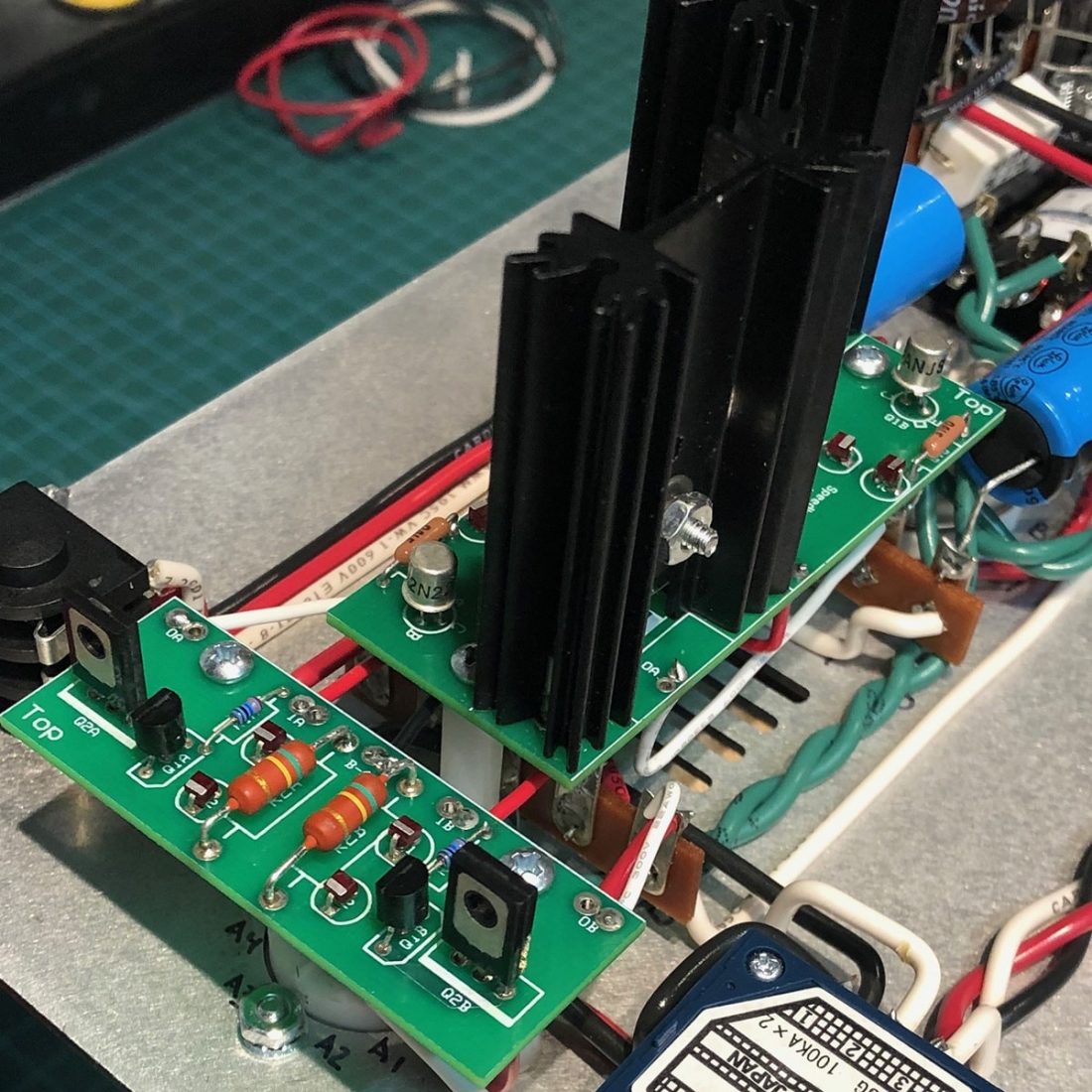
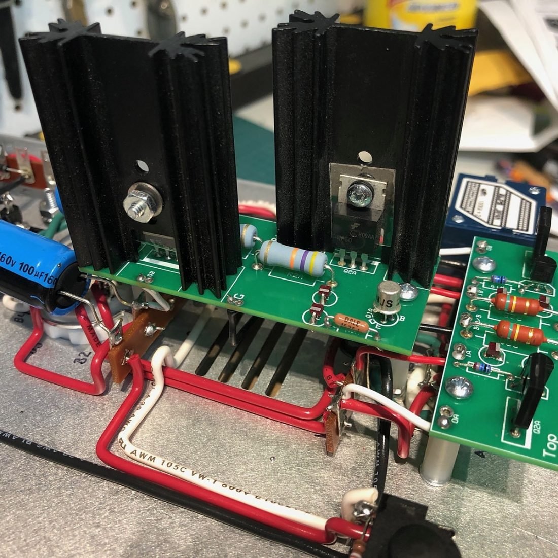
The place to start your upgrade journey is with Bottlehead’s own Speedball kit. The most recent version (v1.1) consists of two circuit boards, associated components, wires, standoffs, and screws. This is a much neater and elegant solution than the multiple board version 1 implementation that I have in my own Crack.
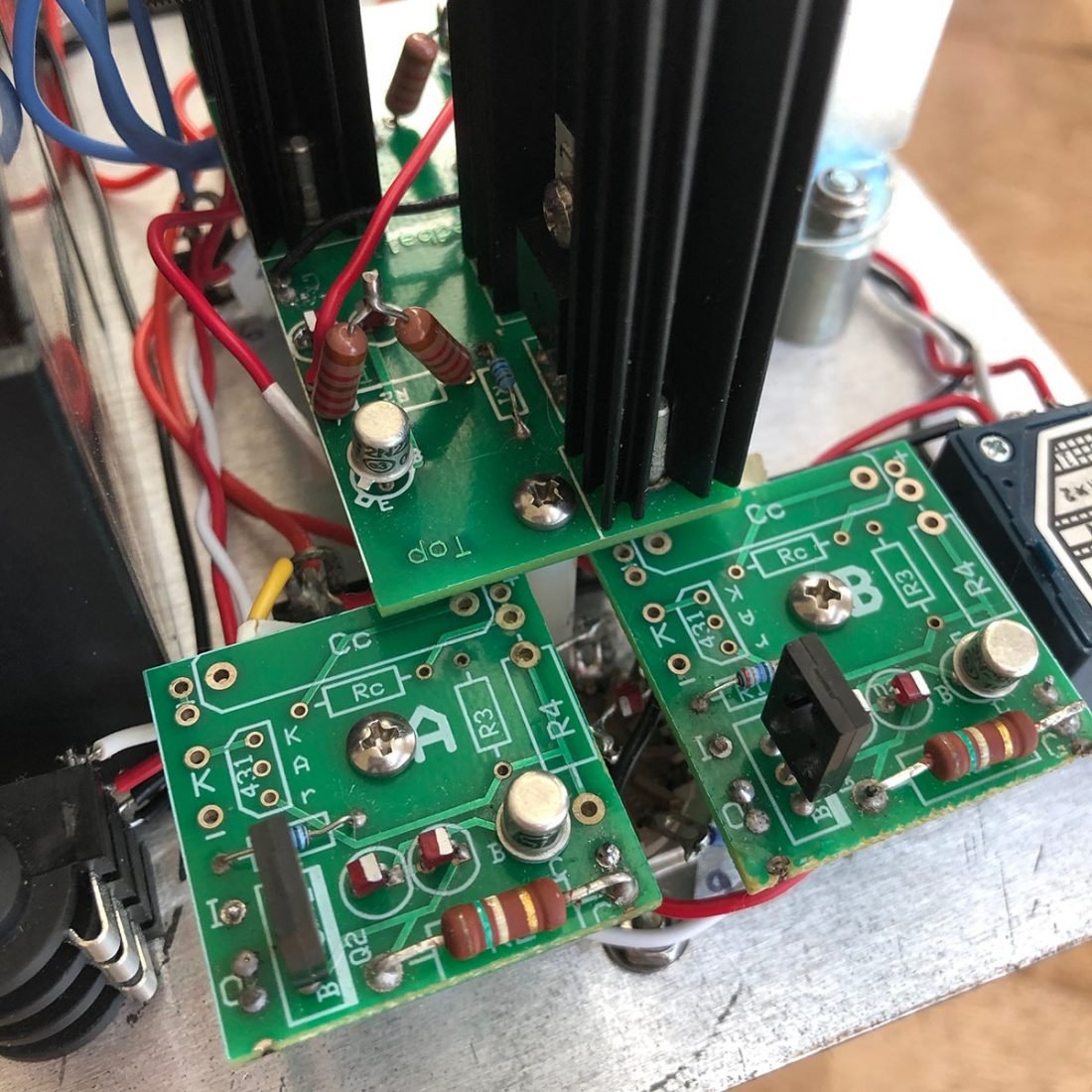
Bottlehead considers this a level 2 kit, meaning it is intended for someone who has some experience and already completed a kit (like the Crack). The process of “stuffing” and soldering a circuit board isn’t difficult, but it is smaller scale and fussier than the Crack assembly.
It should only take you a few hours to complete and install a Speedball. It does require removing 4 resistors from the stock Crack to install. Again, a full set of excellent instructions is included to guide you along.
Bottlehead lists the Speedball as a Camille Cascode Constant Current Source (C4S) design, originally created by the late John Camille (known as Buddha in audio circuit design circles).
Bottlehead states that “the improvement is easily heard” and makes the Crack “quicker, more quiet, [with] better mids, better bass, better resolution.” In more technical terms, the constant current improves isolation of the power supply by about 60dB and keeps the tube in a more linear operating state as it approaches clipping.
From my experience, this is unquestionably a worthwhile upgrade. Background noise is lessened, while clarity and dynamics improve. The overall performance is cleaner and more present.
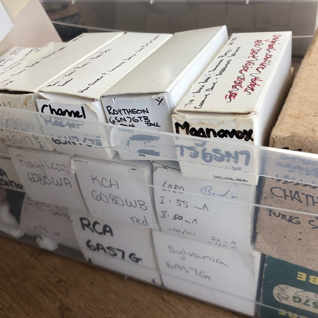
Tube Rolling in the Crack
The Bottlehead Crack circuit uses two tubes. A 12AU7 input tube serving as a voltage amplifier, directly coupled to a 6080 power tube as a cathode follower output. The two stereo channels each use half of the tube. The included tubes are of decent quality and can be expected to provide years of great sound.
However, you didn’t just build a tube amp to not play around with things, did you? Tube rolling is a fun and easy way to tweak the sound to your preferences. It’s easy to get obsessive and spend a lot of money hunting for and collecting the perfect tube. I speak from experience here. Try to remember that in general the changes will be fairly subtle and tubes may sound somewhat different but not necessarily better or worse.
I’ve described tube rolling before as a “type of fixed hardware equalizer (EQ)… a very subtle EQ that cannot be adjusted but only replaced.” From my Op-Amp article “…tube guys are forever collecting esoteric and expensive tubes to try in their amplifiers, all with the intended purpose of chasing that ‘ultimate’ sound. Rolling tubes, while having absolutely nothing to do with physically rolling the round tube down a surface, may have been named from the circular rocking motion used to remove a tube from a socket.”
There are a huge amount of options of different manufacturers and compatible types of tubes. From the very comprehensive 125+ page forum post entitled Tube Rolling w/Crack in the Bottlehead forums:
Drop-In Tube Equivalents
Input Tubes (Original: 12AU7)
- 12AU7(A)(WA)
- ECC186
- ECC82
- ECC802(S)
- E8025
- E82CC
- CV4003
- CV4122
- CV491
- 5814(A)
- 6189(W)(WA)
- 6680 (WL6680)
- 6067
- 7489
- 7316
- 5963 (computer version of 12AU7)
Sort-of-Drop-In (but not equivalent – for best results, replace plate resistors with Speedball boards)
- E80CC
- 12BH7
Power/Output Tubes (Original: 6080)
- 6AS7G
- 6080
- 6H13C
- 5998
- 7236
- 6N13
The Best Tubes for the Crack
So, what are the best sounding tubes in the Crack? Well, that’s the million-dollar question. There are MANY opinions and long posts out there on just about every audio forum.
For power tubes, there is some consensus around the domino plate Tung Sol 5998 as being (one of) the best sounding (albeit expensive) option. I personally often use one, but sometimes swap it for a Bendix/Chatham 6080WB which tends to have a more forward and aggressive sound signature than the smoother 5998.
In my opinion, the tall coke bottle shape of the 5998 is more interesting looking and distinctive than the shorter round shaped 6080.
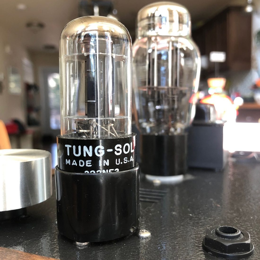
I really can’t find any consensus regarding the ultimate input tube. There are just so many possibilities. Further compounding this, a product like the Garage 1217 6SN7 to 9 pin noval adapter works perfectly to allow the use of 6SN7 equivalent tubes as well in the input socket.
I previously owned a similar OTL Darkvoice 336SE amplifier which uses 6080 and 6SN7 tubes, so I have many of these types of tubes on hand. The Garage 1217 adapter was the perfect solution for me and I tend to use a tall Tung Sol 6SN7 tube as the input tube in my Crack.
Capacitors
In Doc B’s words “…for the stock Crack circuit the two easiest improvements after Speedball are film output caps and a better attenuator.”
Replacing the two output coupling capacitors with higher value capacitors (thereby increasing the capacitance) can be used to avoid bass roll off for low impedance headphones.
Note that changing the capacitance value impacts the output capacitance (and thus bass roll off) and higher or lower values may be substituted. However, the voltage rating on the capacitor is a MINIMUM. Only higher voltage capacitors can be substituted without issue.
Electrolytic vs Film Capacitors
Unfortunately, affordable large electrolytic capacitors are non-linear with regards to frequency, so are a bit of an audio quality compromise. Suitable film capacitors of appropriate voltage are physically very large (think soup can sized) and tend to be expensive.
In theory, all capacitors used in an audio circuit will have an effect on sound quality. It stands to reason that capacitors that are directly in the path of the audio signal (such as the output capacitors in the Crack) have the largest impact on quality. Due to their linear behavior, non-polarized film capacitors are most commonly used in the audio path to minimize any degradation of sound quality.
Some modders do change one or more of the three electrolytic capacitors in the power supply with a film equivalent. Again this becomes an issue of cost and space requirements balanced with any potential benefits.
ESR
Equivalent series resistance (ESR) summarizes all the losses due to resistance within the capacitor, including supply, contact, line and (most significantly) the dielectric losses in the dielectric material. As such, ESR is usually only an important consideration when selecting electrolytic capacitors.
Losses due to ESR will increase high frequency noise, increase ripple, decrease filtering effectiveness, and decrease stability in the circuit. This is another reason to strongly prefer film capacitors in the audio circuit.
Output Capacitor Options
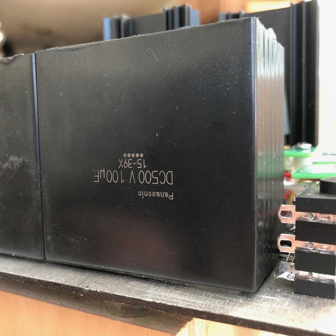
We will discuss potentiometers in the next section, but Doc B’s words above give us a very good starting place for what to look for in capacitors for the output. At the minimum, you are looking for 100uF capacitance and at least a 160 Volts DC rating (stock values). The preference is for film caps, and as you will see, some are rated for ‘audio’ purposes.
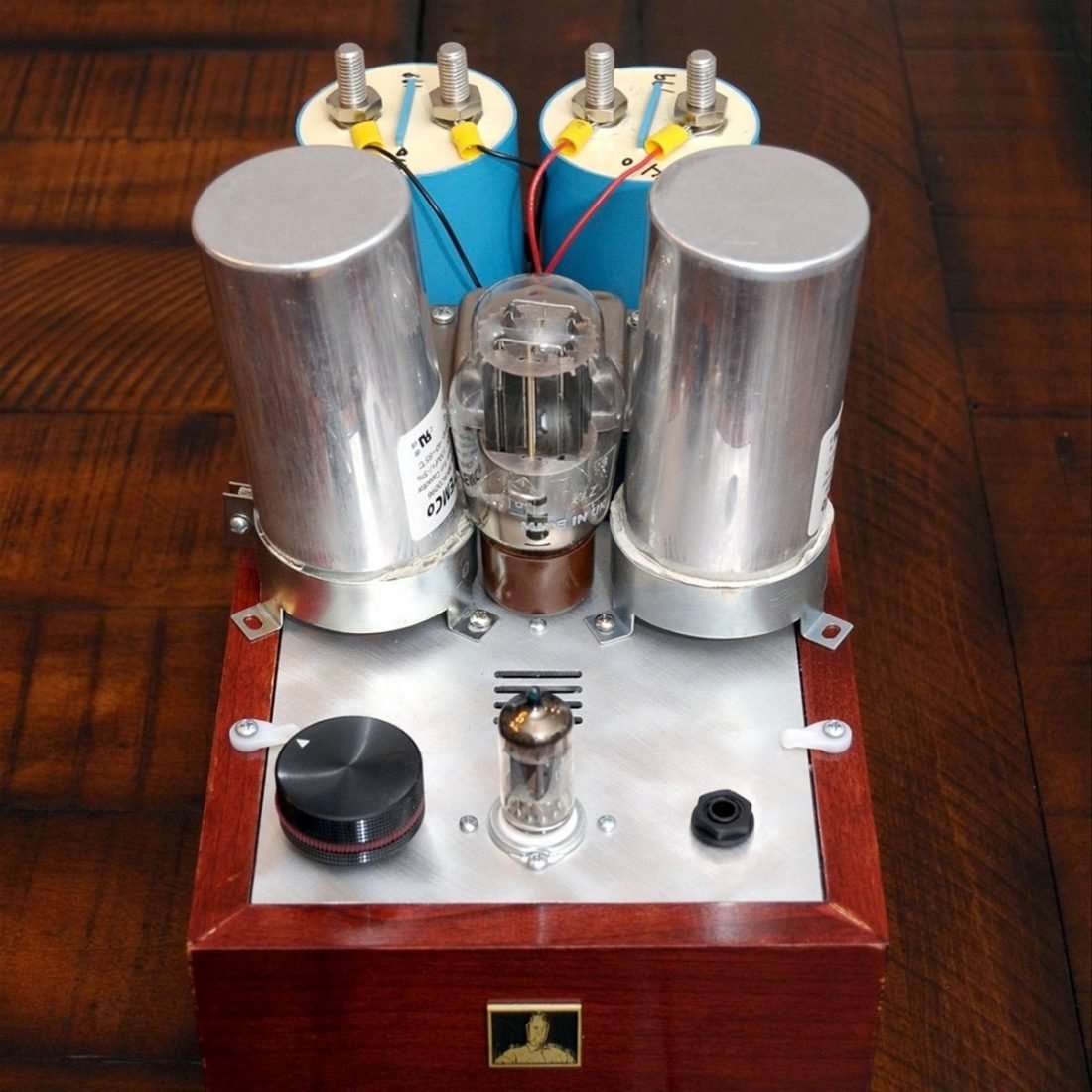
Here are some output capacitor options (by no means an exhaustive list, but it does give you a feeling for the range of prices and sizes). Cans of Coke and condensed soup are included for size comparison. Remember you’ve got to find a way to fit (and mount) two of these under the chassis!
| Name | Cost (each) | Supplier | Length | Width/ Diameter | Height |
|---|---|---|---|---|---|
| Can of Coke – 12 US fl oz | 122 mm | 66 mm | |||
| Can of Condensed Soup | 98 mm | 65 mm | |||
| Panasonic EZP-E50107MTA CAP FILM 100UF 500VDC | $19.86 USD | Digikey.com | 57.4 mm | 35 mm | 56.4 mm |
| Audyn Cap Q4 100uF 400V | $25.76 USD | Parts-express.com | 62 mm | 61 mm | |
| Sprague Capacitor 100uF 350Vdc Atom TVA Series - Electrolytic | $27.30 USD | Partsconnexion.com | 66.7 mm | 25.4 mm | |
| Solen PA10000 100mfd Fast Capacitors 250v PA Series | $30.44 USD | Solen.ca | 65 mm | 49 mm | |
| Jensen Capacitor 100uF 500Vdc Axial Audio Grade - Electrolytic | $33.19 USD | Partsconnexion.com | 49.5 mm | 30 mm | |
| Dayton Audio DMPC-100 100uF 250V Polypropylene Capacitor | $38.99 USD | daytonaudio.com | 75 mm | 51 mm | |
| ClarityCap Capacitor 100uF 250Vdc PX Series | $51.33 USD | Partsconnexion.com | 60 mm | 81 mm | |
| Mundorf Capacitor 100uF 350Vdc MCap® EVO | $60.06 USD | Partsconnexion.com | 50 mm | 75 mm | |
| Mundorf Capacitor 100uF 350Vdc MCap® EVO Oil | $72.10 USD | Partsconnexion.com | 50 mm | 75 mm | |
| ClarityCap Capacitor 100uF 250Vdc CSA Series | $89.74 USD | Partsconnexion.com | 60 mm | 76 mm | |
| Auricap Capacitor 100uF 160Vdc XO Series | $158.16 USD | Partsconnexion.com | 47 mm | 60 mm | |
| Mundorf Capacitor 100uF 350Vdc MCap® EVO SilverGoldOil | $385.03 USD | Partsconnexion.com | 50 mm | 75 mm |
As you can see from my pictures, I decided on the Panasonic capacitors for a couple of reasons. They are the cheapest option (especially with Canadian shipping from digikey.ca). Also, because they are rectangular rather than round, and relatively small compared to the other options, I was able to fit both of them on one side of the Crack’s chassis.
This gained mounting options that most have to forego with the larger cylindrical capacitors. Double-sided tape and a wooden support mounted to the inside of the case work perfectly to hold them securely.
Alternatively, I have complete faith in Doc B’s suggestion of the Audyn capacitors as an affordable substitute. I believe the rules regarding diminishing returns apply strongly here.
Bypass Capacitors
Bypass capacitors are a somewhat controversial inclusion in audio circuits. Whether they improve the audio path, are a potentially expensive placebo, or even a detriment to the sound quality is under some debate. Much like so much of this hobby.
Typically, a bypass capacitor is a small non-polarized film capacitor installed in parallel to another capacitor in the circuit. The bypass capacitor should be of a capacitance of approximately 1% of the original capacitor (and of the same or higher voltage). For example, to bypass the Crack’s two output capacitors, two 1 uF (1/100 of the original 100 uF) capacitors of at least 160 volts can be used.
The theory is basically that larger capacitors are not as good at filling in current spikes and that by paralleling larger and smaller capacitors, it is possible to minimize any unwanted limitations of the capacitor in the circuit.
Without getting too tied up in the theory and mathematics behind it all, bypass capacitor supporters often claim the addition of more “air”, “detail” or “extension” to the high frequencies.
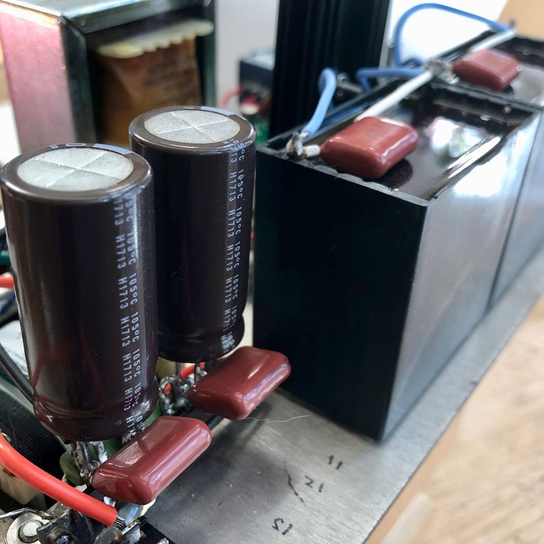
For my build, since bypass capacitors are small in size and relatively inexpensive, I added some utilitarian Panasonic 1 uF capacitors to bypass all the large capacitors in my own Crack. I can’t claim an audible difference, but it fell into the “why not” category as they were cheap and easy to install while doing other modifications. I wouldn’t personally spend a fortune on exotic bypass capacitors, but it is easy to find folks who swear by them.
Replacing the Volume Control
A common complaint with the inexpensive volume potentiometer included in the Crack kit is that there can be a slight volume mismatch between channels at very low volumes. I never really noticed this issue, as at any usable listening level for me was above this minimum. However, one of the first upgrades I did in my own build was to replace the volume control. Why? The end point when turning it all the way down felt a bit “squishy” and not solid enough for my taste.
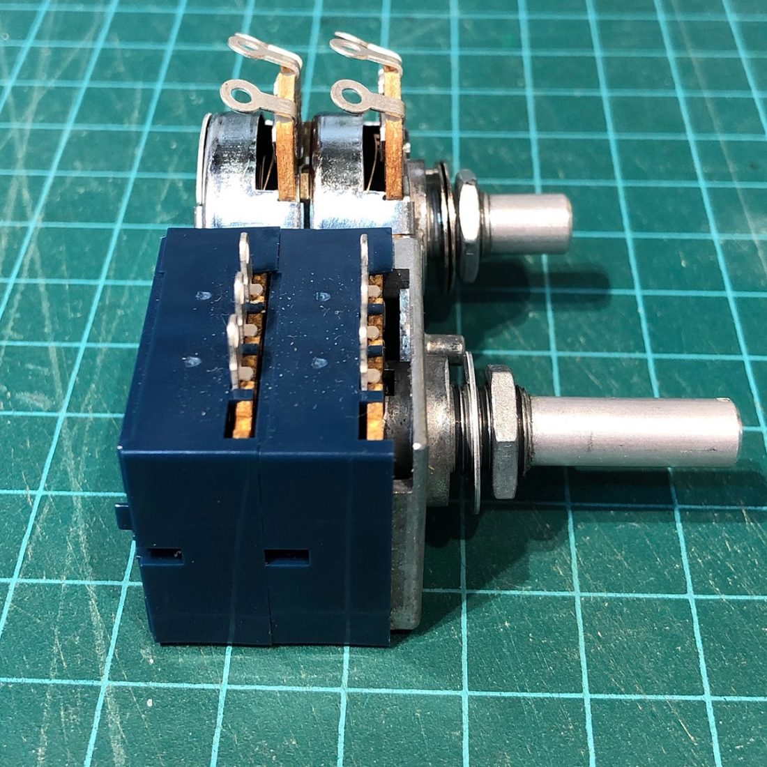
Selecting a new volume control is relatively easy. It must be stereo (2 channel) and logarithmic (which is generally indicated by being described as appropriate for “Audio”). It must be between 25K and 250K in impedance – the stock volume control is 100K.
As we’ve seen, Doc B recommends the Alps Blue Velvet potentiometer as a worthwhile upgrade. It is relatively inexpensive ($20 USD), but is of excellent quality. It is wired into the circuit identically to the original volume control. Speaking from my experience, it looks, feels and sounds exactly like it should.
Here again, the sky is just about the limit if you feel like spending money. Audio Note potentiometers are about twice as expensive ($40). TKD 100K potentiometers are approximately 5x more expensive ($100 USD).
Stepped Attenuators
Stepped attenuators are another higher-level option to put in place of the standard potentiometer volume control. As opposed to a variable resistor (as in the case of a potentiometer), attenuators have discrete resistors arranged in a specific number of fixed steps to lower the volume. Theoretically, this should eliminate channel imbalances, and puts one, (or at most) a very few high-quality resistors into the audio signal path for the ultimate in fidelity.
Supporters of attenuators claim that the sound is more refined, with added resolution and improved high-end clarity. Whether your equipment or your ears are able to discern this level of sophistication is up to the individual.
They also tend to be physically much larger than a regular potentiometer, further adding to the real estate problems in a fully modified Crack.
However, because attenuators have fixed steps, depending on the number of fine increments the attenuator has, it is possible to find that the difference between two positions is going from ‘too quiet’ to ‘too loud’ without the ability to fine tune the volume in between. Obviously, more ‘steps’ is better at minimizing this issue. Options include:
- ConneX 100K Attenuator – 23 steps: $75 USD.
- Khozmo 100K Stereo MkII Design – 48 steps: $180 USD.
- Danish Audio ConnecT (DACT) CT2-2 100K – 24 steps: $220 USD
- Goldpoint V47-2 100K – 47 steps: $246 USD
Other Audio Upgrade Options (aka Things That Doc B Doesn’t Recommend as Worth It)
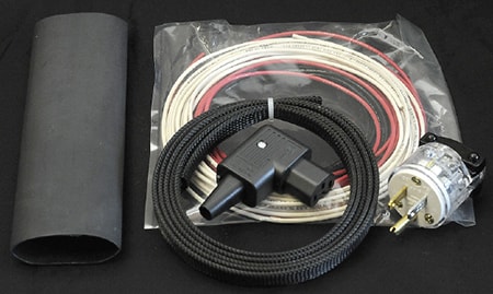
Bottlehead Power Cord Kit
I would be remiss not to mention a little-discussed upgrade for all the Bottlehead kits; namely the power cord kit. The cord kit came about after Bottlehead accidentally ordered several thousand feet of 20-gauge stranded wire. They designed a six-foot flexible cord using twisted pairs of wire that are braided together. It is conservatively rated at 3 Amps (none of their kits use more than 1.5 Amps on start-up and less when running) and has a 120VAC 15A plug.
Bottlehead makes it clear that they cannot scientifically explain the difference in sound and are unwilling to “come up with some far fetched theory like most cable manufacturers.” However, they promise that:
I recently had a conversation with Adam Goldsmith (ohshitgorillas), a headphone and Bottlehead Crack enthusiast, and whose original Crack modification posts inspired my own upgrades and ultimately this article. He told me the following:
“Have you done the Bottlehead power cord? I put it together myself and was absolutely blown away by the improvement in air, space, detail, and soundstage depth. I can hear so much further into the recording it’s wild. Definitely had to eat my words as far as how much difference a power cord can make.”
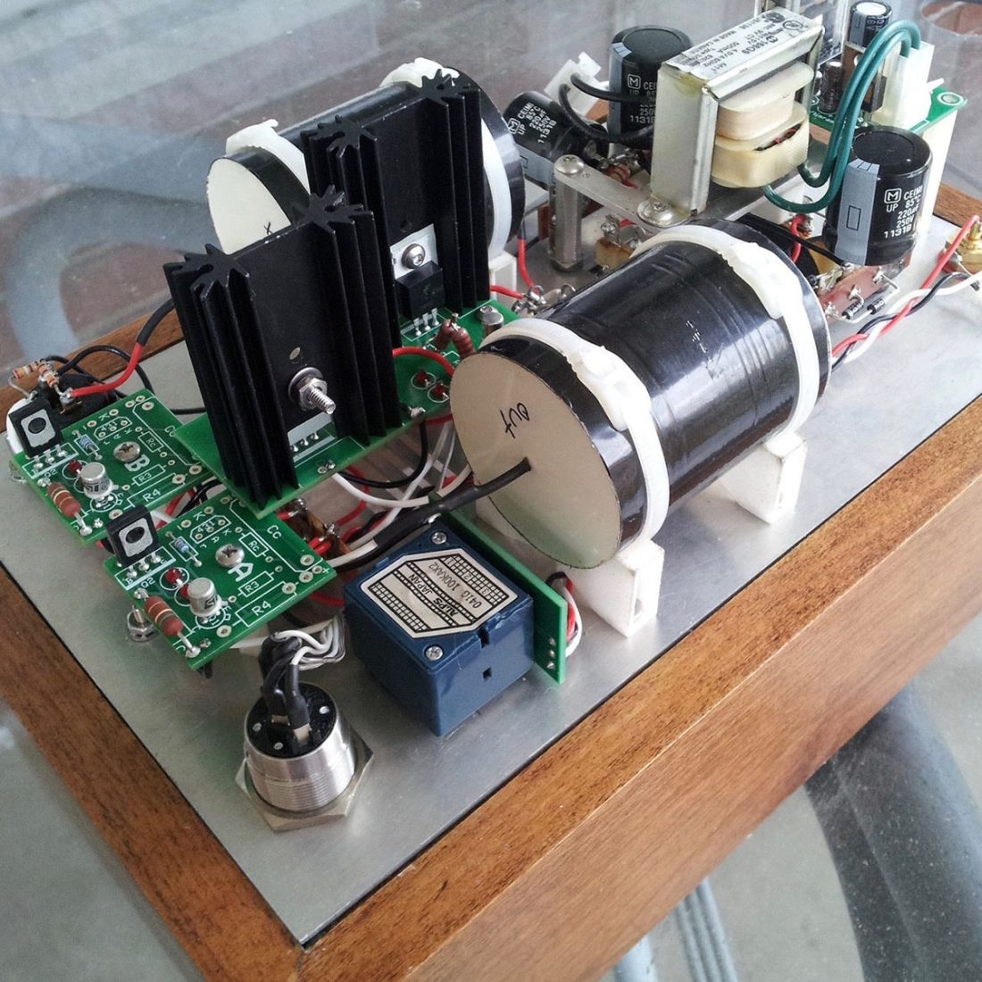
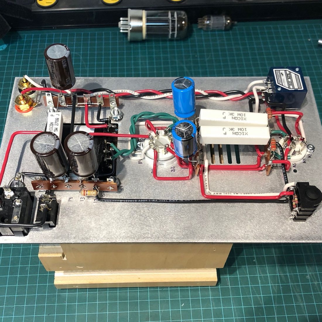
One (or More) Chokes
A choke is an inductor (similar in appearance to a small transformer) that is typically used as a power supply filter. Since the current in an inductor can’t change instantly, the choke acts as a passive resistor (to current) and smooths out any ripples (and as a consequence reduces hum and unwanted noise).
Typically, a choke is used in the Crack to replace the 270 Ohm 5W sand resistor in the power supply. Common options are either the Triad C7-X ($12.22 USD) or Hammond 158M ($21.90) models.
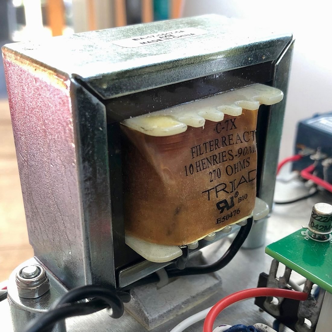
This is another upgrade I did to my Crack because my output capacitor choice and mounting location left adequate space for a choke, and also because the Triad choke was relatively inexpensive. Some modders replace both resistors in the power supply with chokes – and have to find suitable mounting locations for both.
One popular choke mounting position for those using two enormous output capacitors on either side of the chassis, is to attach the choke directly below the power transformer. This has a potential negative side effect of current being induced in the choke due to the magnetic fields generated by the transformer. Making the coil axis perpendicular, or leaving as much physical separation as possible between these two components is recommended to avoid the choke picking up 60 Hz hum from the power transformer’s magnetic field.
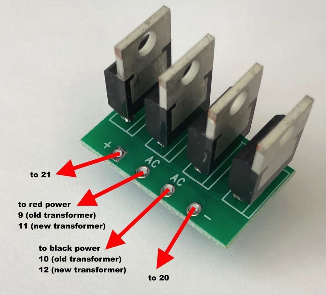
Cree Diodes
Builders have reported better bass, improved definition and lower noise by replacing the 4 stock diodes in the power supply with higher quality Cree Schottky diodes. This requires building and mounting a small daughter PCB board for the new diodes as they will not fit in the original locations.
This is not a modification I have tried myself, but supporters report clearer sound with greater detail.
Conclusion
Since the Bottlehead Crack is a DIY kit, it is possible to replace every component either as you go or after the fact. Think boutique or silver stranded wire will sound better? Go for it. Want ultra-expensive RCA inputs or a locking headphone jack? There are lots of options. How about Teflon and gold tube sockets?
That’s just the insides, you could always change the feet or perhaps a new volume knob is in order.
You really can spend as little or as much as you want.
Diminishing Returns
At what point is enough, enough? Never has diminishing returns been so abundant, when you can literally upgrade every single component. Let’s try to think back to that basic, unmodified Crack you built in the beginning.
How did it sound? Great! Truly excellent!
It’s easy to get caught up in the excitement of researching and tweaking. It’s really fun to build something yourself and to take it to the next level. I caution restraint, as those super high-end (and expensive) upgrades really might be better off spent on a headphone upgrade or even a different Bottlehead kit.
Bottlehead Crackatwoa
Bottlehead offers a better version of the Crack called the Crackatwoa. It costs about what one would spend if you bought a “fancy attenuator, boutique caps and questionable upgrades like a filter choke in the power supply of a Crack kit.” (Doc B’s words.) It features circuit improvements like a better power supply with shunt voltage regulation.
The Crackatwoa is intended as an improved design, rather than just better parts, but doesn’t sell nearly as well as the original Crack. Whether this be because of the more affordable starting price, or the allure of personalization and tinkering that the basic Crack offers.
No piece of audio equipment that you buy from a manufacturer, complete in a box, will ever compare to the satisfaction of something you built and modified yourself.
Your Crack is just that. Yours. Individual. Just the way you want it.
Loving the guide, thanks for the great information! What black shields are those used on the base of the tubes?
That, I’m afraid, is a bit of an industry secret. The tube boot combines excellent insulating properties, tube dampening and stabilization, and as a result deepens bass and extends the highs, while maintaining a focused mid range.
It’s the rubber end of a broom handle that happened to fit and hide the tube adapter. 😉
What a great article. Thank you. I learned so much. I am prepping myself for my first build. Now comes the decision to get the Crackatwoa and a couple of upgrades or just the Crack with a few upgrades.
Thanks Brent! Good luck with your build! I’m sure you’ll enjoy it!
Hi, Having read the blog about the crack ha with great interest I am about to upgrade the amp I inherited a year or so ago.I have the choke, coupling caps and ditched the cheap attenuator (which was a bit ropey) for an Alps pot but I’m finding the wire used very stiff and to exacerbate things it’s also very short, so could you lease advise on any alternatives. Either solid core or multi strands to rewire the unit with something a bit more flexible and of the same or slightly better quality. The signal input to potentiometer has already as a “star quad” type cable at the moment.
The best hookup wire I know is Duland
https://www.partsconnexion.com/DUELUND-81388.html
I used this link just so you know the exact wire to use, I could care less who you choose to purchase it from. The fact that it’s sleeve/insulation is cloth does make it vulnerable so you have to be cautious not to short it out. I got careless with a Stasis amp once and took out a channel. None the less, as long as you are cautious it’s awesome. I have been known to put it in heatshrink. It’s based upon Western Electric cable which once allowed people to talk coast to coast with very clear sound. Western Electric was AT&T’s exclusive source for cable. You can attempt to get original W.E. wire, but it is being counterfeited so Duland, while not inexpensive, is a safer bet. I have been told that the Duland wire is an improvement as well, but while I have some of both, all my interconnects are Duland and my speaker cables are Western Electric, I haven’t been able to A/B them. The W.E. cable is 10 gage, and Duland 12 gage cable would cost more than I am willing to pay these days. I run super efficient speakers and have been told that I can use 16 gage, but I always prefer over kill just to be safe. I will say that I have a very large number of very expensive interconnects, and my Cardas cables were the best of the bunch, and for high end cables they do sound good, but the Duland interconnects cost about $50 or so, depending upon whether they are single ended or balanced, and they are definitely better sounding, for hundreds less, IME.
I slipped, I meant to post this link, the tin coated wire sounds best, I don’t know why. Tin is generally used not for its sonic signature, but to prevent copper from corroding. I can’t begin to say why it sounds better, it just does. This is the link that I had intended to post;
https://www.partsconnexion.com/DUELUND-82235.html
I should also say that if you use it in a stereo system that lacks detail, you may never hear a difference. Also, it’s possible that a cable can mask issues, but none of that should apply to the Crack with good headphones.
Honestly, I wouldn’t overthink the wire. Solid core 24AWG-18AWG will work fine. Differences aren’t likely to be audible IMO.
Thanks for the advice looking forward to:firing it up in the new year
Cheers
Excellent article Trav, thank you!! A question on the output capacitors. You state as reason for considering upgrading them:
“Replacing the two output coupling capacitors with higher value capacitors (thereby increasing the capacitance) can be used to avoid bass roll off for low impedance headphones.”
For higher impedance headphones, such as my Sennheiser 800s or Beyerdynamic T1 gen 2, would there be any appreciable improvements with an upgrade to film capacitors, or would it only help for setups with low impedance phones?
Thanks again!
Bypassing lesser quantity caps with better quality caps, IME, has always made improvements. Best bang for your buck would be Miflex KPCU-01 or 02 capacitors, though you are going to think I am crazy for perhaps 100 hours. I should also mention that if a circuit sucks, the Miflex KPCU-01 or 02 will expose its weaknesses too. You can do better, but they are crazy good for the money.
Thanks Trav,
You can also use hexfreds in the p.s. Unless you use a snubber circuit, normal diodes ring, this is usually manifested as a “muddled” midrange for lack of a better term. I put hexfreds in any audio gear that I want to upgrade and the mids particularly always clear up. Do yourself a favor, if you are still using the Crack, and install some soft recovery diodes, or convert over to a tube rectifier.
Thanks for the excellent articles Trav, I took a lot of your advice when building my Crack, and it came out really nicely. I ended up grabbing that 12AU7 to 6SN7 adapter you linked to and a NOS Tung Sol 6SN7 off eBay. It sounds SO much better than the stock 12AU7 tube, and eliminated some background noise I was hearing. So thanks a bunch for the tip!
One question though: it looks like you have some sort of cover around your adapter. How might I best fashion a similar cover? The adapter kind of sticks out like a sore thumb compared to the rest of the build.
Thanks again!
That, I’m afraid, is a bit of an industry secret. The tube boot combines excellent insulating properties, tube dampening and stabilization, and as a result deepens bass and extends the highs, while maintaining a focused mid range.
It’s the rubber end of a broom handle that happened to fit and hide the tube adapter. ????
You made my Christmas with that reply to the tube boot.
Thank you very much,
Glad to hear it! Cheers!
Thank you for sharing this fantastic information. Being a student I found it very helpful for me. I am looking to power a circuit that has LEDs. Should I use a boost voltage regulator ? Found this https://www.derf.com/an-overview-on-voltage-regulators/ article that says boost regulators are used to power LEDs, just wanted to check before I bought one.
Thank you for the guide. I have a question on the EZP-E50107MTA. I bought it and it has 4 pins. Could you help on how to wire this? Which pin go to which terminal? Thanks.
Just use one pin from either side and cut off the other pin, as per how I did it in the pictures above. The pins are shared on either end. Hope that helps!
Thank you much. Another question is that i notice you use Panasonic 1 uF capacitors for all the bypass. Though the three back caps are 220, is it required to use 2.2 uF? I have some Panasonic 1 uF capacitors but wonder if i should get different ones.
No hard rule there for bypass cap values. Some folks swear by 0.1uF or 1uF… it’s not going to make a very significant difference IMO.
Thank you much. I see that you use Panasonic 1uF capacitors to bypass. The three back caps are 220, do I need to buy the 2.2uF? I currently have some 1uF i wonder if i should use these or buy new ones.