
The popular DIY budget amp has graduated and fully realized its potential.
The first Starving Student hybrid headphone amplifier originally debuted in 2008 on Pete Millett’s DIY Audio Pages. Pete had gained notoriety in DIY and headphone enthusiast circles by publishing tube, solid-state, and hybrid amplifier designs online and by making them public domain. Pete’s previous creations were highly praised, and when he designed the original Starving Student, he had a new agenda.
The Starving Student II (SSII) shares the same basic architecture as the original. It’s a triode voltage amp, with a MOSFET source follower that is loaded by the tube heaters. It differs from the original primarily in two ways: using 18FX6 tubes rather than the 19J6 (due to availability shortages of this tube) and with the addition of a switchable plate load between resistive or Constant Current Source (CCS).
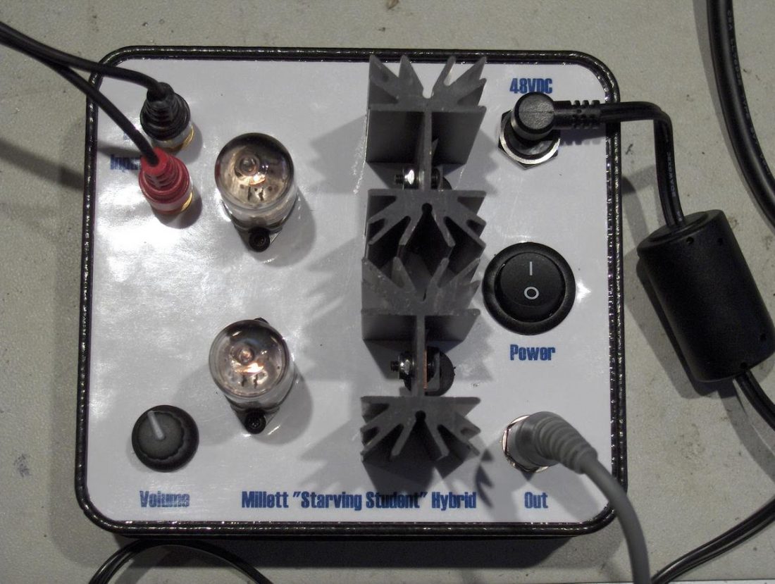
Many folks built the original Starving Student on a shoe-string budget with point to point wiring and salvaged cases. In contrast, the Starving Student II is available from diyAudio Store (in collaboration with Pete) as a Printed Circuit Board (PCB) with all components and a chassis. It’s a polished and professional product that is at odds with its austere namesake.

This article will discuss:
- Building the Starving Student II. How to populate the printed circuit board (PCB) of this beginner-friendly tube amplifier kit.
- Assembling the aluminum case available from diyAudio Store.
- Reviewing objective measurements, and my subjective opinion on how it sounds.
Before we dive into this new tube project, and to better understand where this design comes from, let’s first take a look at the designer – Pete Millett.
Who is Pete Millett?
Pete is a self-professed ivy-league engineering school dropout. He is an electrical engineer and for almost 40 years has done board-level hardware design for computers and consumer electronics.
As a hobby, he’s been designing all sorts of tube audio gear and sharing it with the world. Pete has created headphone amps for Headroom, written for audioXpress magazine and started several audio businesses (Wheatfield Audio and Apex Hi-Fi).
The Starving Student II Amplifier
As mentioned above, Pete’s original goal was to produce a good sounding, inexpensive and easy to build DIY headphone amplifier. Currently, the SSII is available from diyAudio Store for $119 (PCB + components) or for $229 including the case.
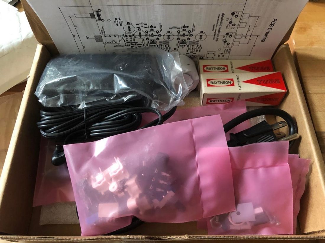
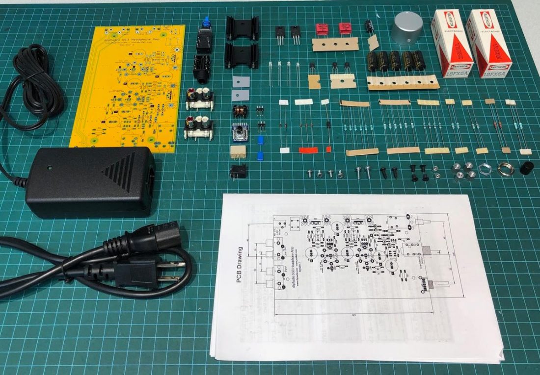
By ordering the SSII kit from diyAudio Store, the preparation work is already done for the builder. There is no need to carefully peruse a Bill of Materials (BOM) to select and order the right components – they all come in the kit, neatly bagged and ready for installation.
One of the aspects that I like most about DIY is that you can often ask questions directly to the designer and, in some cases, assist with the development of a project. Pete is a regular contributor to the Head-Fi and diyAudio forum discussions. He frequently answers questions and provides assistance, even though he does have a standard disclaimer:
“In ALL of these cases, I make no profit from any of the sales. Zero, zip, nada. I have a normal “day job” that pays the bills, this is strictly a hobby with me. So please do not expect me to provide the level of technical support that you might expect when buying a product.
I try and help, but it sometimes takes me days – even weeks if I’m traveling for work – to respond.” – Pete
Starving Student II Specifications
| Spec | Plate Load | 150 ohm load | 30 ohm load |
|---|---|---|---|
| Gain (at max volume setting) | CCS | 20 dB | 18 dB |
| Resistor | 17 dB | 16 dB | |
| Frequency response +/-3dB | CCS | 11Hz - 40kHz | 18Hz - 40kHz |
| Resistor | 12Hz - 50kHz | 20Hz - 50kHz | |
| Frequency response 20Hz-20kHz | CCS | +/- 0.8dB | +/- 1dB |
| Resistor | +/- 0.8dB | +/- 1dB | |
| THD+N 1V 1kHz | CCS | 0.47 % | 0.15 % |
| Resistor | 1.8 % | 1.3 % | |
| Maximum output @ 5% THD | CCS | 9.9 V RMS | 2.5 V RMS |
| Resistor | 3.1 V RMS | 2.4 V RMS |
Starving Student II Circuit and Design
The amp uses a pair of 18FX6 tubes (functioning as triodes) as a voltage amplifier stage. The SSII design uses a MOSFET source follower (also known as a buffer or common-drain amplifier). The gate of the MOSFET is biased such that there is about 18V on the source terminal of the MOSFET, which is loaded with the 18FX6 tube heaters.
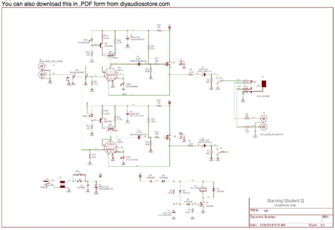
The input signal is applied to grid #1 after the volume control and the plate AC is capacitively coupled to the output stage.
The output RCA jacks are deactivated when a headphone plug is inserted in the jack. Both headphone and RCA outputs are muted for approximately 15-20 seconds upon start-up to eliminate any ‘thump’ noise from capacitor charging.
The 18FX6 Tube
The 18FX6 is an uncommon tube choice for a headphone amplifier as it was traditionally used in radios (they were used in the last generation of the “All American 5” tube radio). It is a pentagrid converter, which in Pete’s words “turns out to make a pretty decent amplifier if you connect it as a triode”.
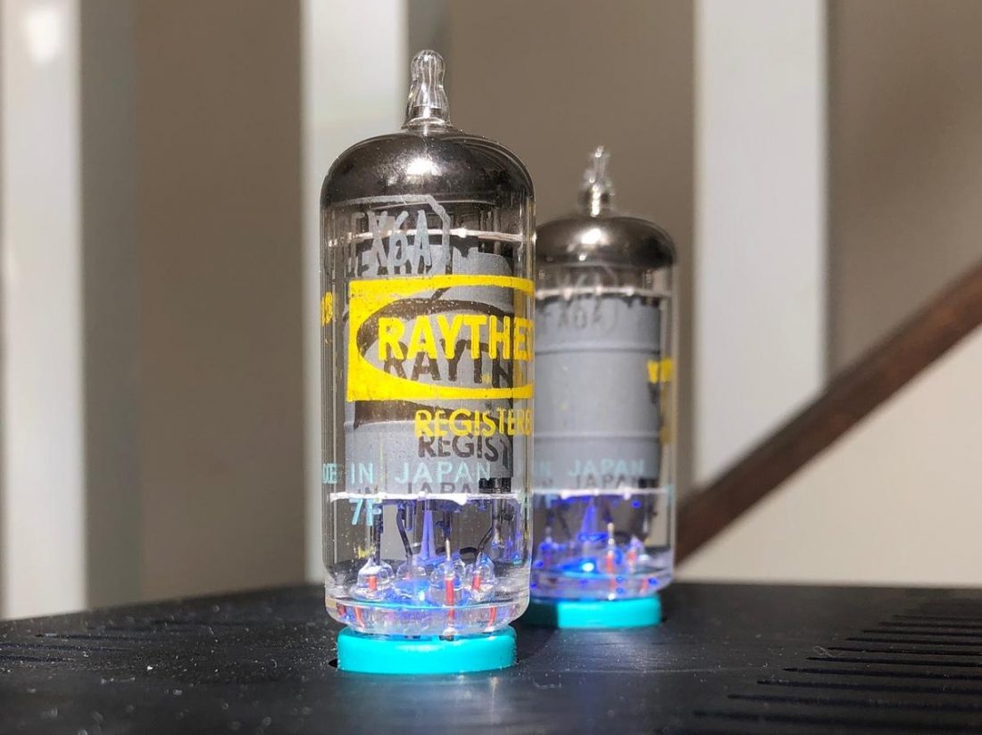
Pete purchased thousands of the 18FX6 tubes after the original Starving Student tubes became difficult to source. They are all ‘new old stock’ (NOS) from a large master case and likely 1960’s vintage. Most are labeled Raytheon and were made in Japan, although Pete says he has examples from just about all the manufacturers (RCA, Sylvania, Westinghouse, etc.).
Pete expects that the tubes should last between 5,000-10,000 hours. Although the tubes included in the kit are not ‘matched’, all measure just about identically (Pete reports of the ones he’s measured, the gain was matched to about +/-0.2dB).
The 18FX6 tube is rated at 18V and 0.1A across the heater (very similar to the first Starving Student 19J6 tube rated at 18.9V and 150mA). This means the SSII has the same 48V DC 0.625 power supply requirements as the original and has plenty of current to drive most headphones with ease.
“In case you’re wondering, yes, it’s OK to put audio on the tube heaters. Think about it – normally they run on 19V RMS AC. In this case, they’re running on 19V DC, with a little bit of audio superimposed (rarely more than 1V or so).
There could (theoretically) be a little coupling from the filament to the cathode – the cathode resistor is un-bypassed – but it would be negative feedback, and the capacitance from heater to cathode is so low compared to the cathode resistor it would probably only be measurable at RF frequencies.” – Pete Millet
Selectable Constant Current Source or Resistive Plate Loading
To increase flexibility in tuning the sound of the amplifier, Pete changed the design of the SSII to include a pair of jumpers to select between resistor or CCS plate loading. The jumpers are accessible by removing 4 screws from the bottom of the chassis (if using the diyAudio kit).
CCS Benefits
- Lower distortion
- Increased linearity
- Increased gain
Resistor Benefits
- Softer clipping
- Traditional tube sound
CCS Biasing LEDs
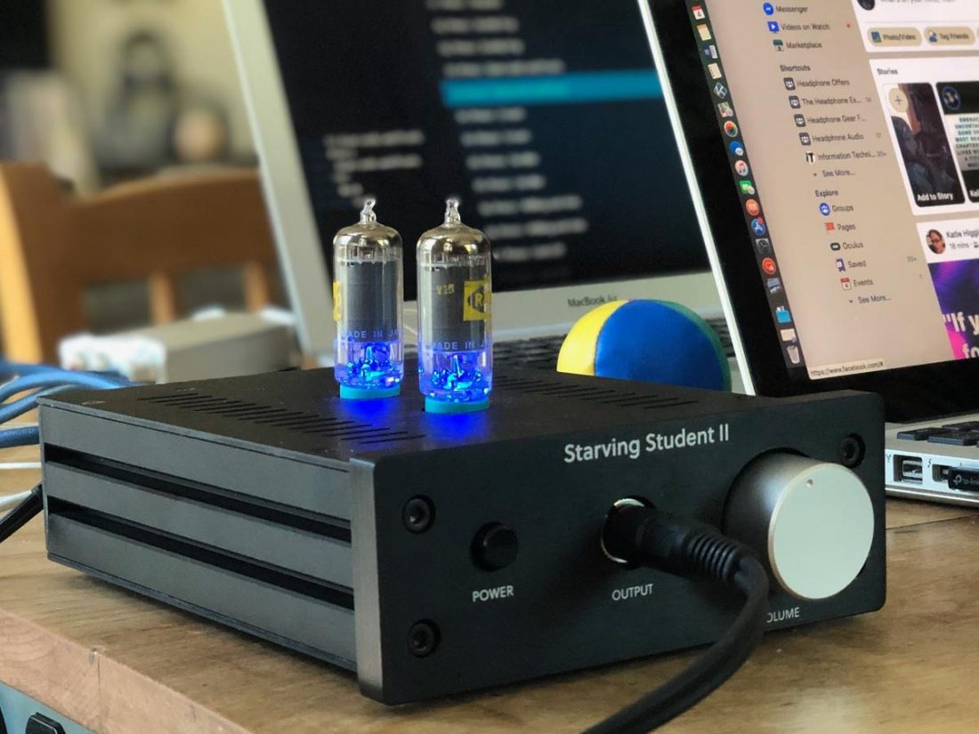
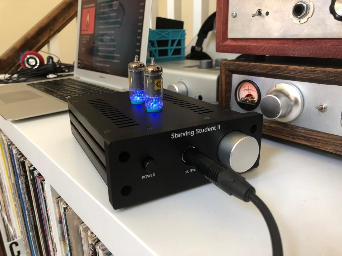
The CCS uses a PNP transistor, biased with two blue LEDs which are also used to light the tubes from below. Unfortunately, for many enthusiasts who love the glowing tube aesthetic, the 18FX6 tubes have little to no glow on their own.
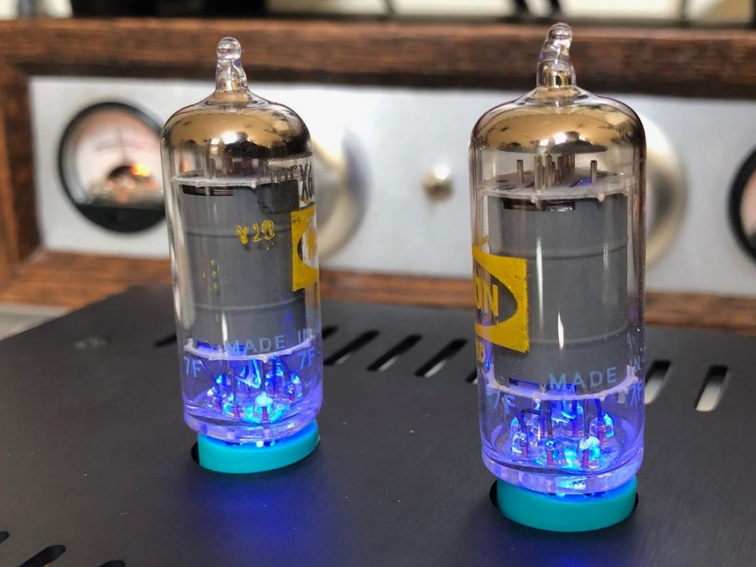
In this case, since the blue LEDs are used in the circuit, it makes sense to also use them to shine up through the tubes. This provides a bit of visual interest and functions as a power indicator.
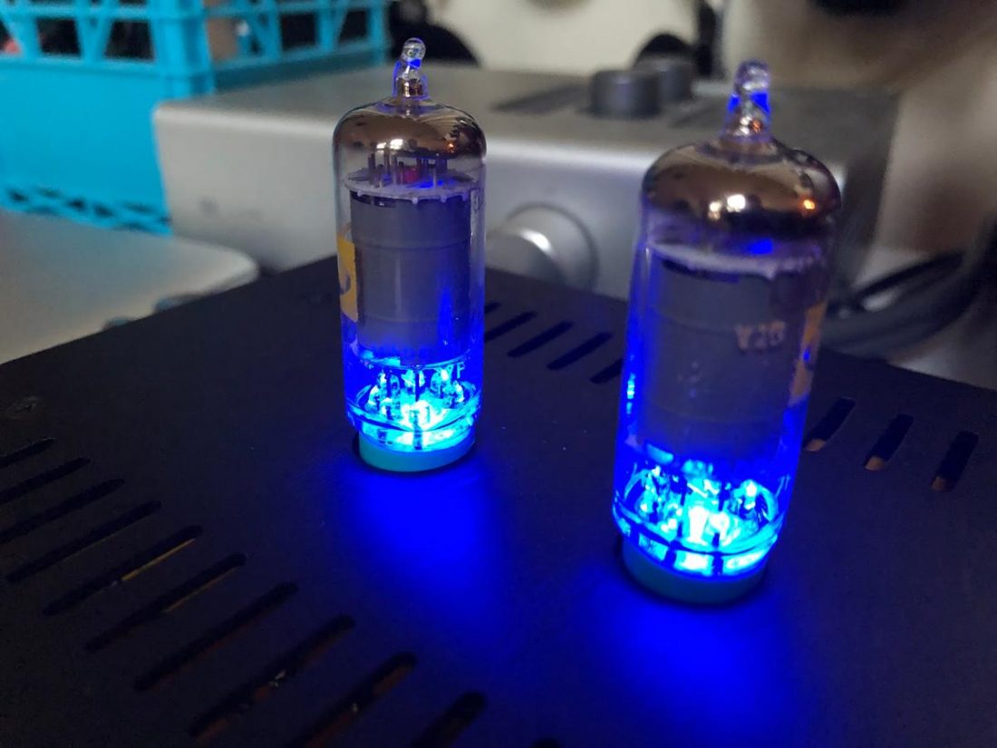
The blue color is a controversial choice. In a recent discussion on the Headphone Audio group on Facebook, (although there were a few positives) the overwhelming response was negative.
“I am not a fan at all, just seems gimmicky to me.”
“Tacky blue LED’s look cheap imo.”
“Don’t like it personally, looks cheap. I much prefer the natural glow of tubes.”
Many expressed a preference for a different color, preferring a more natural orange or yellow tint to appear like a glowing tube filament.
However, Pete participated and explained why changing the LED color isn’t possible with this circuit design:
.
Of course, you can mount the LEDs inside the chassis (on the other side of the board) so they don’t show.
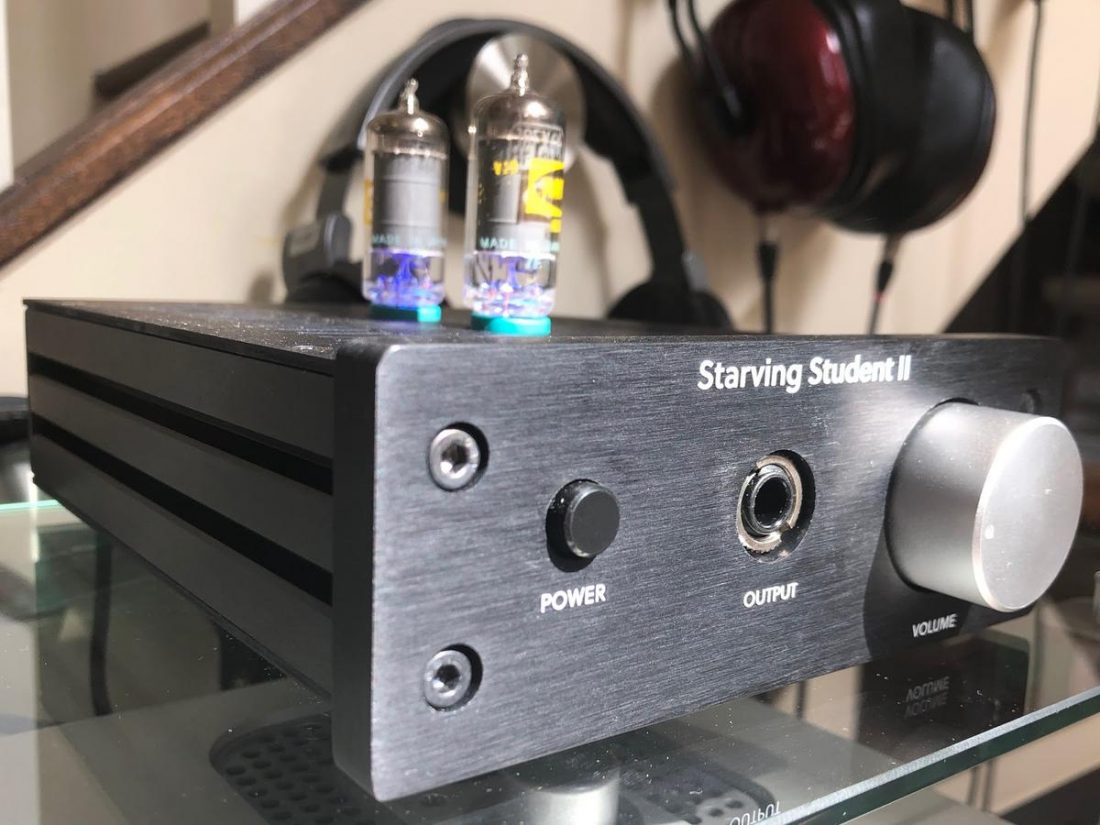
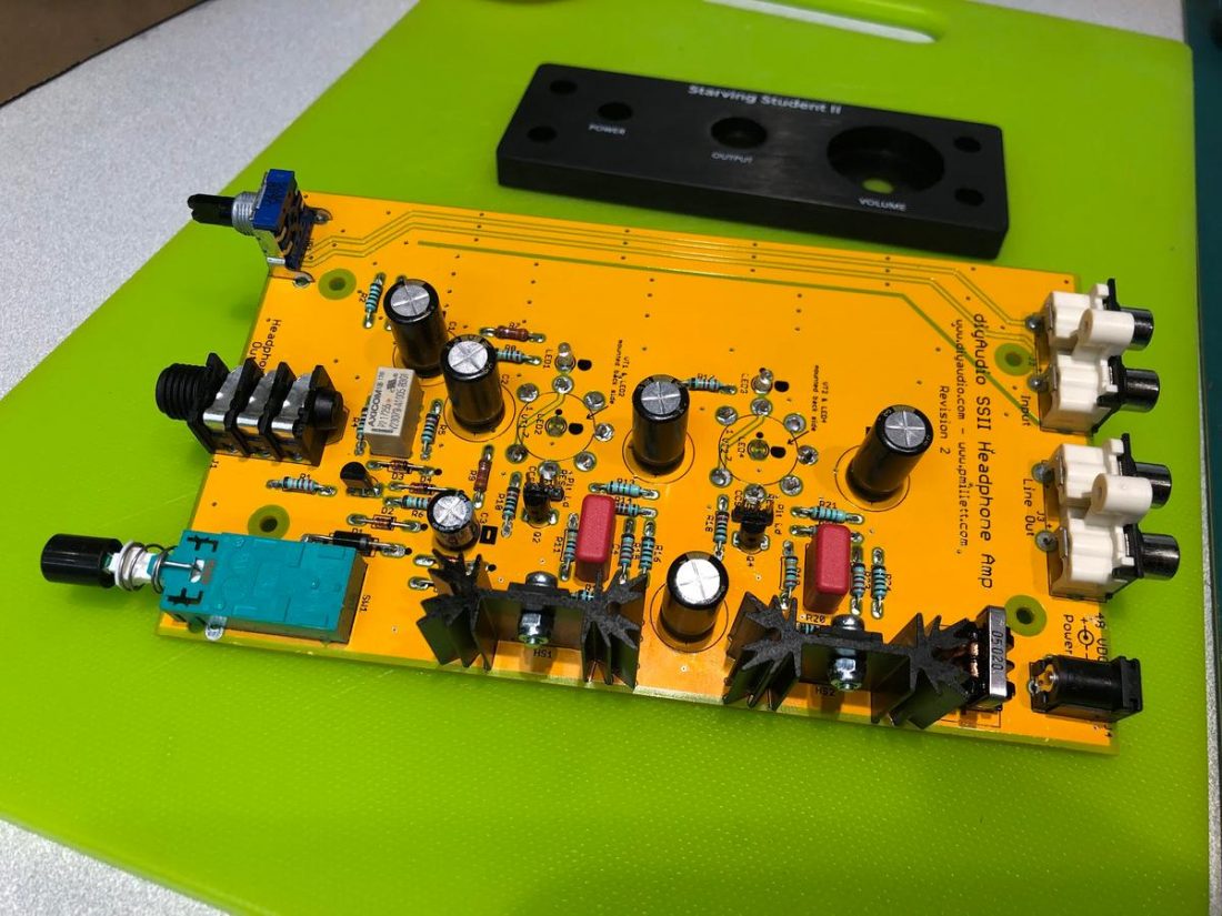
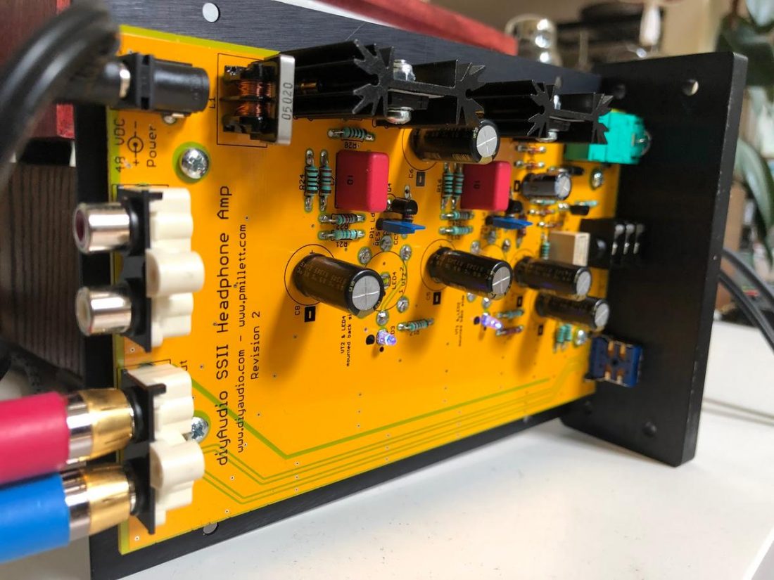
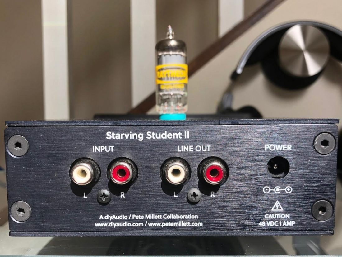
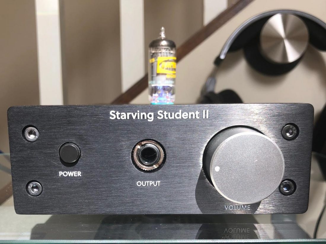
Starving Student II Aesthetics and Quality
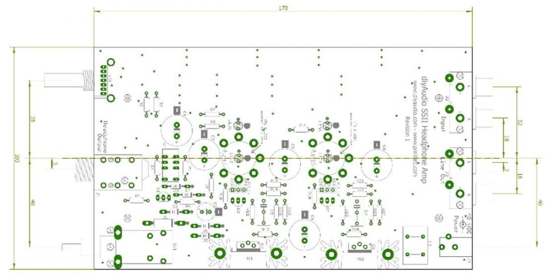
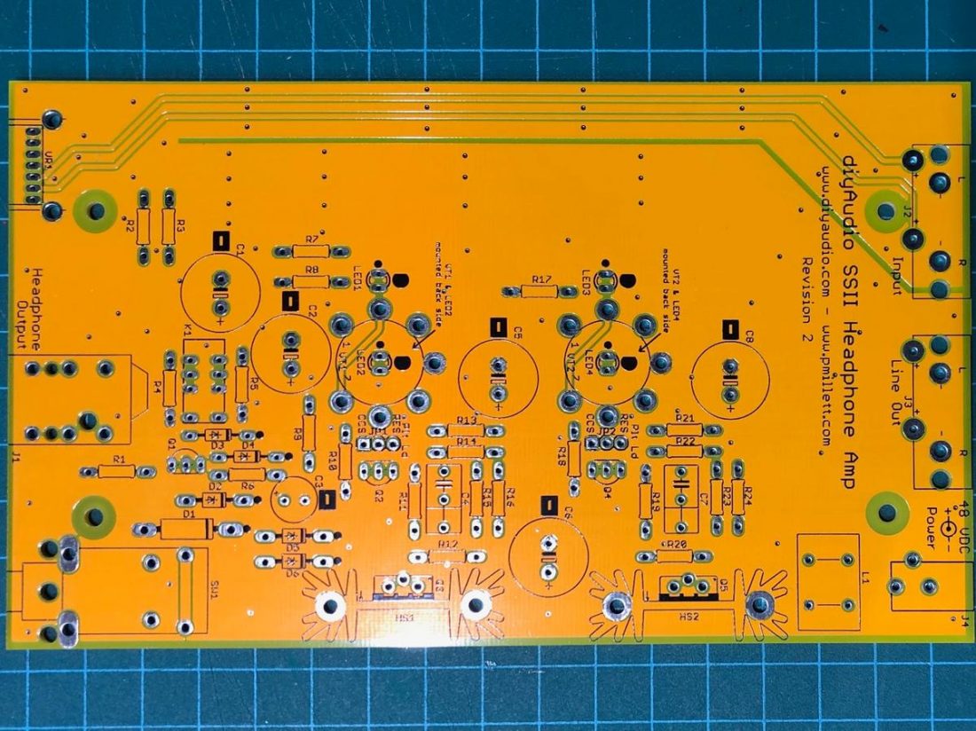
The diyAudio kit is of excellent quality. The printed circuit board is attractive, thick, intelligently laid out and clearly labeled. All you can ask for in a PCB.
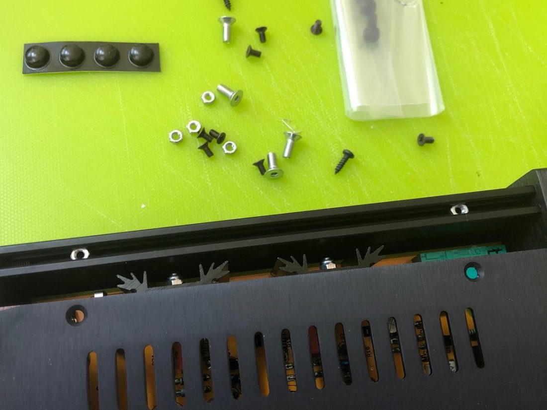
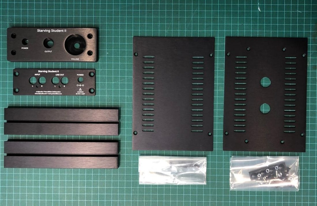
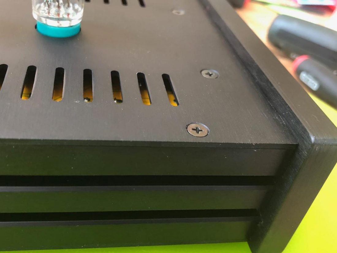
The aluminum case is made in Italy by HiFi 2000, a company that has produced precision-milled electronic cases since 1977. The case features a 10mm thick, black anodized, aluminum front panel. All cuts and edges are perfectly done and smooth to touch. It’s held together with a combination of (included) Philips and hex screws, which fasten the top, bottom, front and back to the side pieces.
The volume knob is fashioned from satin-finished solid aluminum. The power button is black plastic.
The completed kit is fairly diminutive in size. It’s about 5.25 inches wide and 7.75 inches deep (including the volume knob). The case is 2 inches tall and the small 18FX6 tubes add about another 2 inches in height. It weighs approximately 1.75 pounds so, with its rubber feet, it isn’t likely to move around on your desktop.
Assembling the Starving Student II
Building the SSII is a very straightforward affair that should only take a few hours to complete. Assembly is helped immensely by following Pete’s excellent assembly instruction manual. As always, take your time, read carefully, and check your work. You should have very few issues completing the build.
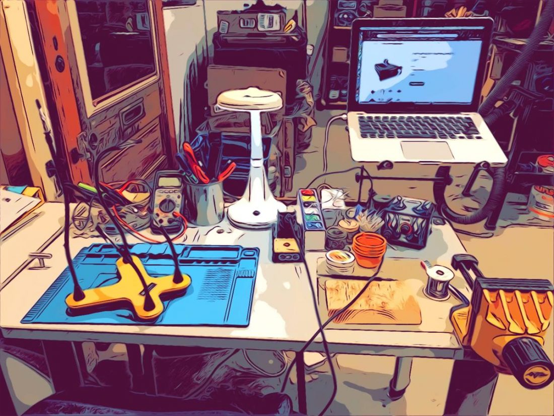
To populate the SSII PCB, you will need a few basic tools:
- Soldering iron
- Solder – Tin/lead 63/37 is recommended.
- Wire cutters
- Fine tipped needle nose pliers
- Digital Multimeter (DMM) to test
To assemble the case:
- Phillips Screwdriver
- Metric Allen (hex) keys
Experience is not necessary to build the SSII, as this is designed to be a basic kit to assemble. However, a little practice soldering would be beneficial to not damage components or the PCB. With some care and careful following of instructions, this project is entirely appropriate for a first-time builder.
PCB Population Instructions
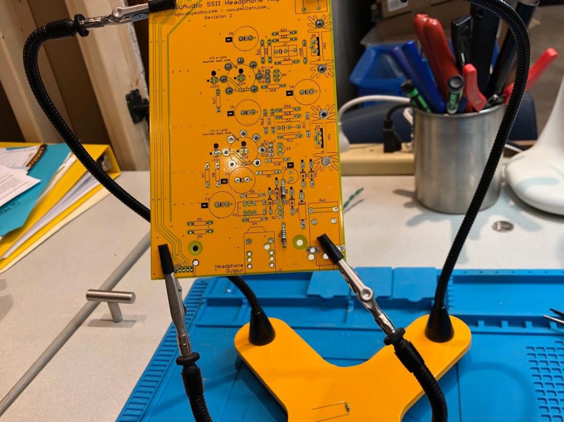
Assembly of the components on the PCB can happen in any order, however, the instructions organize things to install the lowest profile components first and work up through the taller parts. Parts are numbered from the lower-left corner when the PCB is positioned so that the writing is the proper orientation.
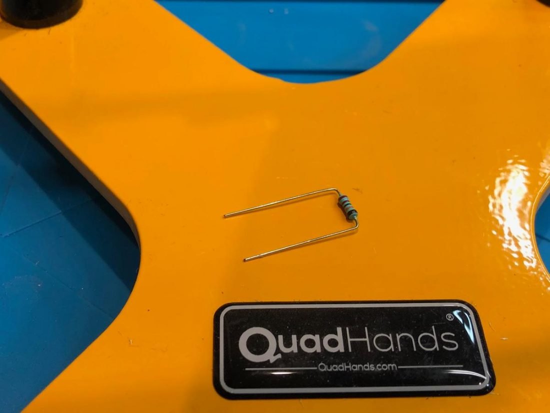
While the leads of components can be bent with your fingers, I find that more attractive results are obtained if I estimate the distance between mounting holes by eye, and then bend the leads to perfect 90-degree angles (using needle nose pliers) prior to insertion.
In general, to populate a PCB with components, each component is inserted in the board from the top through the appropriate holes. The component is pulled down to be flush with the top of the board and the leads (tinned metal wires extending from the component) are gently bent outwards on the back of the PCB to hold it in place. This temporarily holds the component in place and readies it for soldering.
The soldering iron is momentarily touched to heat the solder pad on the board and the lead evenly and at the same time. Solder is applied to the hot pad and lead, which liquefies and creates a small, neat mound. If done properly, the solder cools to a cone shape and hardens to encompass the pad and hold the lead securely. The excess lead beyond the solder is then trimmed off using wire cutters.
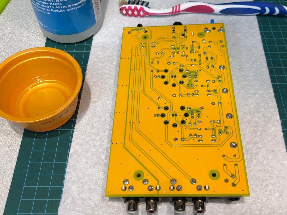
This is just a quick overview of the soldering process, and there are many excellent in-depth tutorials available if you are new to soldering or want to learn more.
Repeat until all components are attached, triple-checking before applying solder for all components (capacitors and diodes) that have to be oriented properly for polarity.
Starving Student II Order of Installation
The instructions walk the builder through installing (in order):
- Resistors
- Diodes
- Transistors
- LEDs
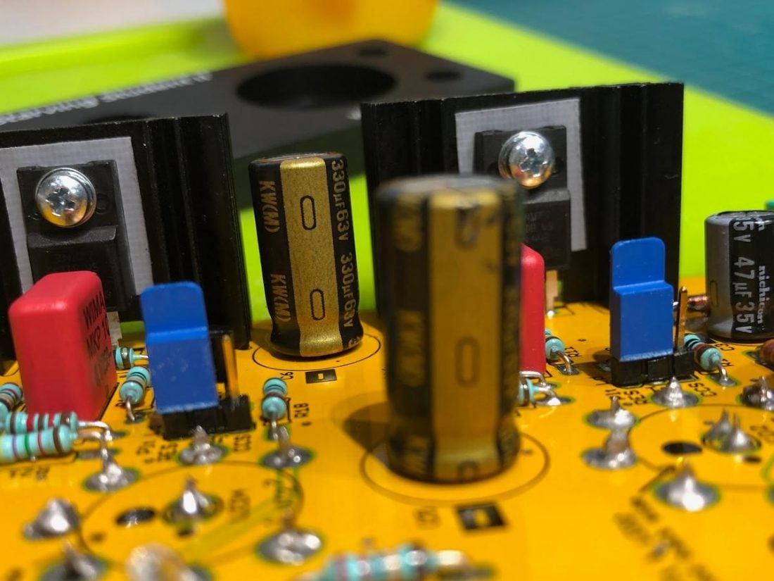
- Heatsinks and power MOSFETs
- Film capacitors
- Electrolytic capacitors
- Choke
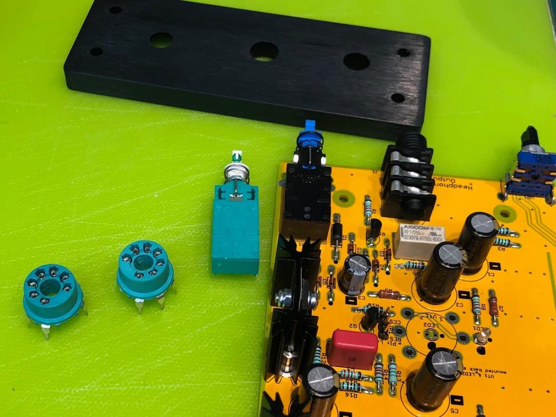
- Input and Output RCA jacks
- Power jack
- Power Switch
- Volume Control
- Headphone jack
- Tube Sockets
- Tube LEDs
- Jumpers
- Push-button power cap
Power On Test
Before plugging in the tubes, it’s time to do a couple of easy power tests, or as the manual calls it ‘smoke tests’. If you are unfamiliar, ‘letting out the magic smoke’ is a common DIY joke referring to improper connections burning up components.
Once the board is fully assembled, and DOUBLE-CHECKED AGAIN, it’s just about time to plug it in and push the switch. First place the board on a non-conductive (wood, paper, plastic, etc.) surface and plug in the power adapter. Without plugging in the tubes, depress the power button to turn it on and the tube socket LEDs should light up.
Next, use your Digital Multimeter (DMM) and measure the DC voltage between ground and pin 3 on each of the two tube sockets. This should measure between 18.5 and 19.5 volts (this value will be somewhat lower after the tubes are installed).
If all checks out, find your test headphones. Power the amp off. Insert the tubes and connect the headphones and a source. Utter a quiet and quick prayer to the deity of your choice and power it on. Finally, give it a listen.
Remember to power the SSII off (and I’d suggest unplugging it) before changing the jumper settings between CSS and resistor.
Case Assembly
Assembling the case is purely a matter of lining things up and tightening screws and nuts. The case is very high quality and lines up perfectly. If things aren’t working out, double-check orientation and carefully start again.
The instructions walk the builder through installing (in order):
- Board standoffs
- Top plate and sides
- PCB
- Bottom side panel nuts
- Rear panel
- Front panel
- Headphone jack nut
- Volume knob
Starving Student II Upgrades
There are few potential upgrade options when assembling the SSII PCB, and I’d recommend restraint. This is intended to be a low-cost kit, and subtle or questionable upgrades for much more money is rather beside the point.
Additionally, the kit includes high-quality components from reputable suppliers. However, DIYers tend to be tinkerers, so there may be some room for swaps to be made.
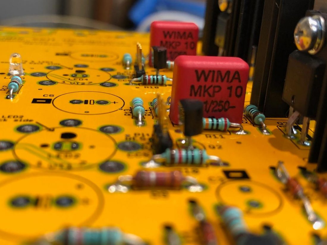
Capacitors
The default capacitors are all very good Nichicon electrolytic caps and Wima polyethylene film caps. It may be difficult to find better capacitors that will fit on the PCB, especially if the diyAudio chassis is used.
Power Supply
A linear power supply can be used in place of the suggested switching power supply, “…assuming it has reasonable filtering and/or is regulated so that it doesn’t have a lot of 120Hz output ripple. 120Hz ripple will probably cause more audible artifacts than the switching regulator ripple.” – Pete on Head-Fi
RCA Connectors
The stock RCA jacks are basic non-gold-plated versions. Off-board mounting will require separate insulated connectors and a custom case.
Volume Control Potentiometer
Although the volume control on the SSII is small and inexpensive (typically a recipe for poor performance)I found it to have reasonable channel balance and be relatively free of noise. This is a great improvement on the stock potentiometer included in Pete’s NuHybrid kit.
Starving Student II Performance and Measurements
I’m happy to report that the SSII achieves a balance between gain and power. All too often I find desktop amps either are unable to deliver enough power for difficult to drive headphones or have far too much audible hiss (any hiss is too much hiss for me) when paired with highly efficient IEMs.
Impressively, the SSII maintains a great balance. It’s really got sufficient power to drive most any full-sized headphones but maintains a quiet background for efficient IEMs. It works well to easily muscle any of my full-sized headphones including the power-intensive Beyerdynamic T1 (600 Ohm, 104 dB) and (Fostex T50RP modification) the MrSpeakers Alpha Dog (50 Ohm, 98 dB).
The T1 or Alpha Dog achieves a loud listening volume at approximately ½ on the SSII’s volume control. It has plenty of power on hand for any of my full-sized headphone needs, yet it retains a silent background when used with efficient IEMs like the Mee Audio MX4 Pro (12 Ohm, 103 dB) or the KZ ZS10 Pro (30 Ohm, 111 dB).
Starving Student II Frequency Response
The diyAudio page includes a pack of 12 SSII graphs and measurements, for both CCA and resistor modes, driving 30 and 150 Ohm loads.
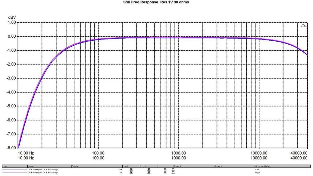
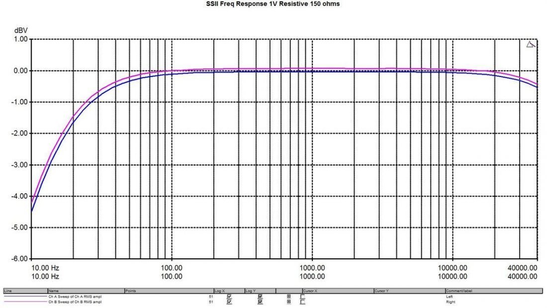
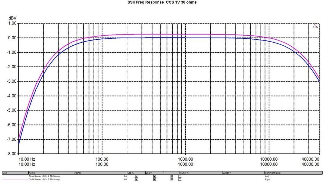
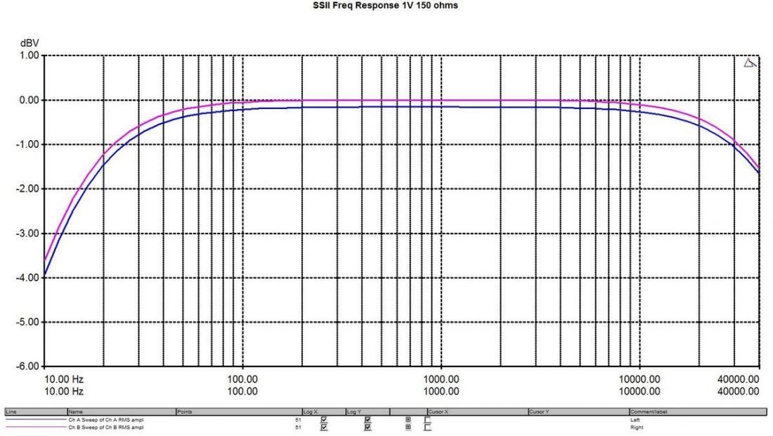
All measurements show relatively similar results and the frequency graphs are remarkably flat. The worst-case low-frequency response is -3dB at 20Hz for a 30 Ohm resistor coupled load. The high-frequency HF response drops over 20-30kHz for all.
In personal listening, I have to concur. I experienced no audible anomalies with CCS or resistor loading testing with a variety of headphones.
Tube Amps and Harmonic Distortion
Tube amps are not theoretical “ideal” amplifiers that simply apply voltage gain. With a tube amplifier, it is important to understand that harmonic distortion is part of the intended sound signature. Harmonic distortion may be defined as the presence of frequencies in the output signal that are not present in the input signal. These frequencies may be even or odd.
Single-ended circuits are asymmetrical, so they tend to create more even harmonics, while push-pull circuits are symmetrical, so they tend to create more odd harmonics.
Harmonics may be seen at 2nd, 3rd, 4th, etc levels. Higher-order harmonics tend to be more audible (and thus less desirable) because they are further from the original frequency. 7th order harmonics and above are considered very undesirable as they tend to be harsh-sounding.
Even harmonics are typically considered more pleasant-sounding than odd harmonics. The desirability of low-level, even harmonics is why 2nd order harmonics are often touted as “what you want” with a tube amplifier.
Of course, personal preference and the music listened to, may lead one to prefer the sweet, tube-like characteristics of even harmonics, or the more-detailed, brighter sound of odd harmonics. Lower-order harmonics tend to mask higher-order harmonics, but higher-order harmonics tend to be more audible, and as we noted above, less pleasant sounding.
So a typical “good sounding” tube amp will try to minimize total distortion, and make sure the higher-level harmonics are at a smaller amplitude than lower-level harmonics (typically in a stair-step pattern downwards).
Harmonics are measured using a Fast Fourier Transform (FFT) graph which displays a signal both in the time domain and the frequency domain. The harmonics of a signal’s frequency appear at higher frequencies than fundamental frequency on the FFT graph.
Starving Student II Sound Quality
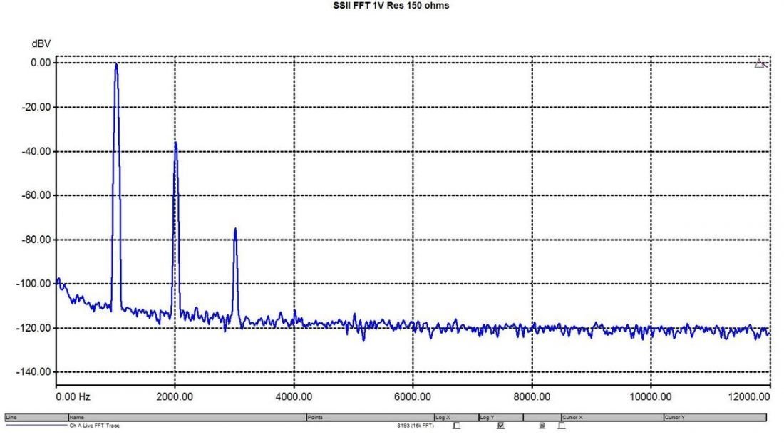
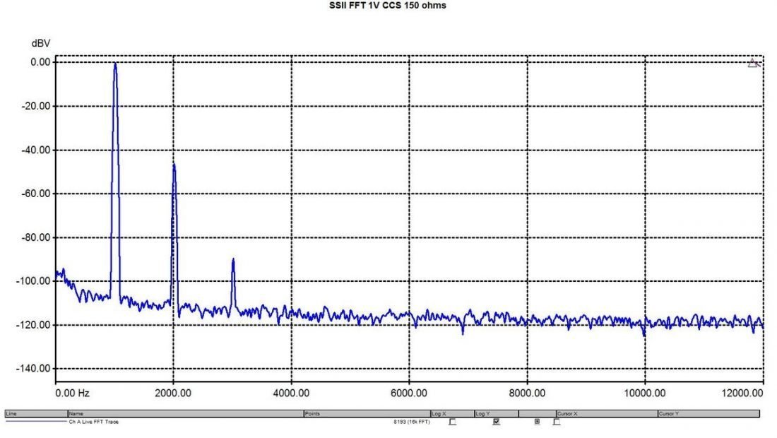
The SSII output displays traditional single-ended triode amplifier characteristics with strong 2nd order harmonics and subsequently smaller higher-level harmonics. This is somewhat stronger with the resistor loading, but the CCS graph displays similar results.
When I asked Pete what he wanted the Starving Student II to sound like, he told me “…like a single-ended tube amp. Think 300B or 2A3.”
Now here’s the thing. I find the SSII to have a very clean and vibrant sound, with little to no background noise. Very similar to decent solid-state amplifiers I’ve used.
Perhaps a little too similar. If anything, I find the SSII somewhat less ‘tubey’ sounding than I expect. Resistor load is my preference (over CCS) but honestly, the sound is not dramatically different between modes.
The SSII tends to feel bright and I found it borderline a bit sharp with some headphone pairings and song choices. Electronica through the Fostex planar headphones was not a great match. I asked Pete what his headphone suggestions are, and it jives pretty well with what I experienced.
If I set my expectations for super warm harmonics aside, there is much to like about the SSII sound quality. Clean, clear, and transparent with plenty of power. Equally adept with my perennial favorite Sennheiser HD650s and the newest IEMs.
Conclusion
The Starving Student II kit from diyAudio is a pleasure to build. It’s got everything that a novice DIYer could hope for: one-stop ordering for all parts, excellent instructions, and an active forum to ask for help. Not to mention, the SSII is a proven design from one of the foremost names in DIY tube amplification and design: Pete Millet.
All the variables have been streamlined to simplify the build experience. Depending on your level of skill, this may be exactly what you are looking for, or you may find it somewhat limiting. The superb enclosure is, on one hand, perfect for the kit, and on the other hand, limits what modifications or upgrades can be done.
The SSII may be a perfect first foray into tubes for solid-state amplifier aficionados. Or it may not capture the tube experience enough. It all depends on your point of view.
Don’t get me wrong, the SSII is a great amp. It’s got many happy customers and excellent reviews. It just wouldn’t be my first recommendation for someone looking for that exalted warm distortion of tube amplification (or the illumination of tube glow).
The sound of the SSII matches the blue LED tube lighting to some extent. A bit too clinical for my personal tastes.
The SSII certainly doesn’t have the look or feel of a cheap product. In no way does it project the “I could stop working at any moment” vibe of many DIY projects. The entire experience is clean, high quality and no-nonsense from beginning to end.
If you want an affordable project or tube amp that you can build and immediately use with a variety of headphones (and with minimal fuss) then the SSII should certainly be considered.