
How a Fluorescent Display became a Triode Vacuum Tube for Audio
The NuHybrid is (as you may have guessed from the name) a new type of hybrid tube headphone amplifier. This relatively little-known kit is based on the original “Millett Hybrid” headphone amplifier design from 2002, but instead of using a traditional old car-radio tube, it uses a Korg Nutube 6P1. Like the original, the NuHybrid employs a low-voltage tube stage for voltage amplification and a solid state OpAmp to drive current to the headphones.
This article will discuss:
- Building the NuHybrid. How to populate the printed circuit board (PCB) of this excellent and unusual tube amplifier kit.
- Since the finished kit leaves the builder with an exposed board, we will also take a look at what’s involved in building an attractive solid wood and aluminum case to fully house the NuHybrid.
- We will examine an intriguing new DAC (Kahdas Tone Board) that can be included in the wooden case to create an ‘all-in-one’ DAC + amplifier unit.
- Finally, we will take a look at objective measurements, and I’ll share my opinion on how it all sounds.
Before we dive into this new tube project, and to better understand where this design comes from, let’s first take a look at the designer – Pete Millett.
Brief History of the Millett NuHybrid Headphone Amplifier
Who is Pete Millett?
Pete is a self-professed ivy-league engineering school dropout. He is an electronics engineer and has worked as a board-level hardware design engineer for more than 30 years. More recently, Pete has moved into a technical marketing engineer role for a semiconductor company. As a hobby, he’s been designing all sorts of tube audio gear for a couple of decades or so. He’s created headphone amps for Headroom and written for AudioXpress magazine.
In 2015, a new type of audio vacuum tube, the Nutube 6P1, was announced by the Korg company. Pete arranged with Korg to distribute the Nutube to the DIY community and small manufacturers through www.nutube.us.
It didn’t take long for Pete to start designing projects around the Nutube. In addition to the NuHybrid headphone amplifier, Pete offers a balanced preamp/headphone amplifier, a 50 watt hybrid class-D amplifier and a stereo buffer based on the Nutube.
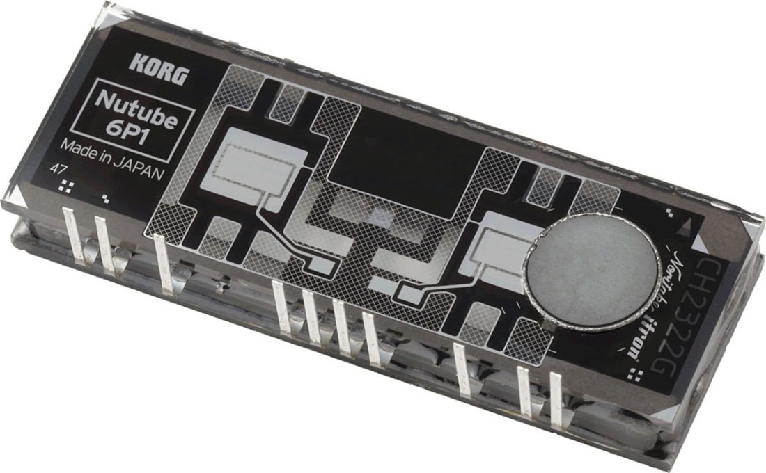
The Nutube 6P1
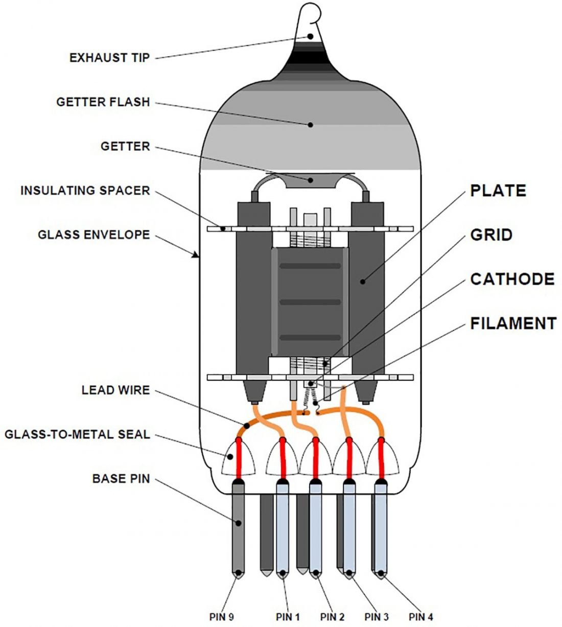
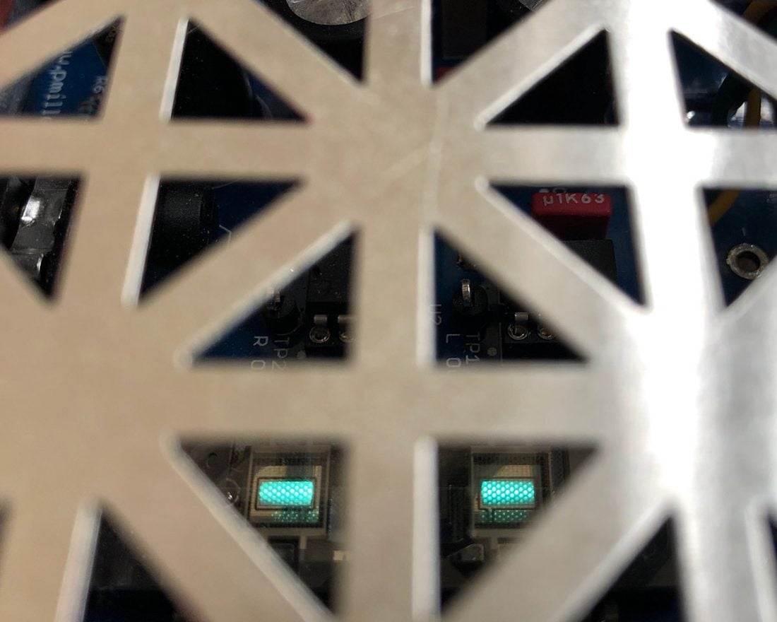
Korg partnered with the Noritake company to develop an entirely new type of dual triode vacuum tube. In some ways, the Nutube is very similar to a conventual vacuum tube. It uses an anode grid filament structure and creates the same characteristic warm “tube sound”.
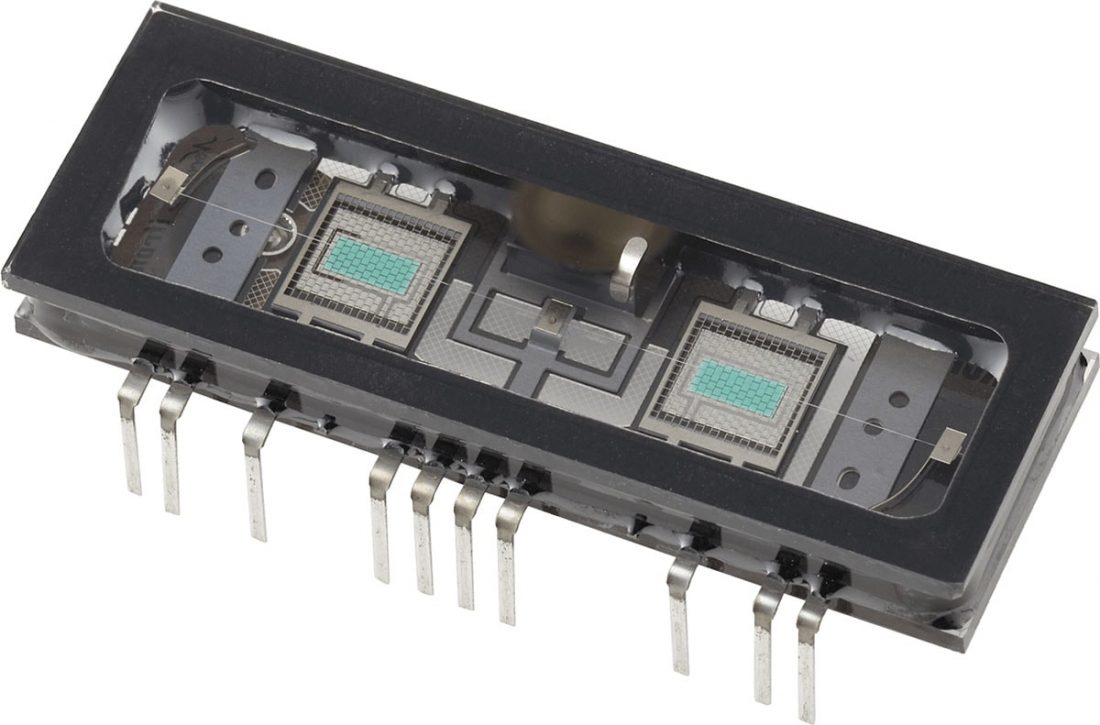
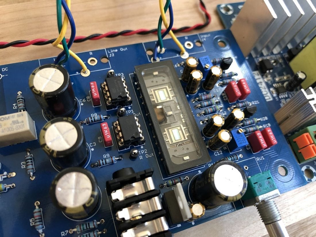
However, the Nutube does not physically resemble a traditional tube. It is built in Japan, using a process originally used for Vacuum Fluorescent Displays (VFDs). This yields a small flat box (45 mm x 16 mm) with two small rectangles (phosphor coated plates) that glow bluish-white when the tube is powered up. Technically, it is a one-pixel VFD.
Korg intends the Nutube to be used in headphone amplifiers, guitar amplifiers, guitar pedals, synthesizers, and preamplifiers. They offer an official premade evaluation board, including a Nutube 6P1 mounted on a PCB for $150, which can be used as a headphone amplifier or it may be placed in line between devices such as a source and amplifier. Korg has also recently released the HA-Kit portable headphone amplifier kit for $250 on Ebay.
Benefits of the Nutube 6P1
Improved Quality Control
The manufacturing equipment that is currently used to produce traditional vacuum tubes has often been in use more than 50 years. This leads to defective units and inconsistent characteristics between tubes. This new design uses improved manufacturing techniques.
Low Power Usage
The Nutube requires less than 2% of the electrical power of a conventional tube. It uses only 12 mW per channel so it is suitable for battery powered operation.
Low Temperature
The Nutube does not generate heat when in use.
Reliability and Long Life
The Nutube is rated for 30,000 hours of continuous use.
Small Size
The Nutube is less than 30% of the size of a conventional vacuum tube. The flat shape is easier to design enclosures around than traditional tubes.
Vacuum Tube Sound
The real triode structure produces warmth and harmonics with excellent linearity.
Drawbacks of the Nutube 6P1
Cost
At $50 it is more expensive than many traditional driver tubes.
Low Transconductance
Triode tubes and derivatives (tetrodes and pentodes) are transconductance devices. This means a controlling signal of voltage is applied to the grid and the resulting amplified signal is current. This requires a low impedance source to drive the grid.
High Microphonics
The Nutube is directly-heated, which significantly reduces power consumption and heat generation. Unfortunately this also means it is VERY easily affected by vibrations and will create an audible metallic pinging noise when moved or tapped.
Korg does suggest ways to try to prevent microphonic noise from external vibrations, transferred either through the mounted circuit board, or even transferred through the air around the tube. They suggest inserting some cushioning (like a sponge or soft equivalent) between the Nutube and the main circuit board, and to connect it using soft and thin wires.
Korg further recommends enclosing the Nutube in a protective box or case and using acoustic material in the enclosure around the Nutube. They go so far as to suggest placing a heavy metal plate (such as lead) on the surface of the Nutube to reduce noise. Not great for aesthetics or seeing the tube glow.
Technical Specifications
- Operating Voltage: 5 – 180 V
- Operating Temperature: -40 – 85 degrees C
- Heater Voltage: 0.7 V
- Heater Current: 17 mA
- Price: $50
The NuHybrid Amplifier
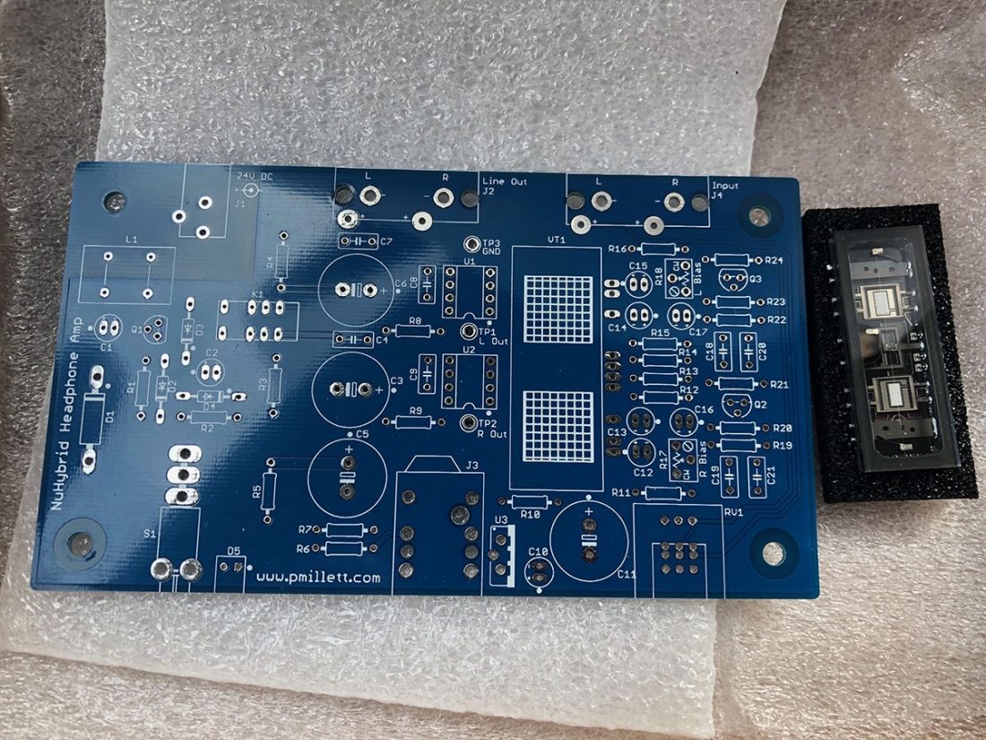
Pete estimates that to build the NuHybrid amplifier, including the minimal bottom case, to cost about $115. He offers the bare NuHybrid PCB including a Nutube 6P1 on Ebay for $50, essentially giving the board away for free with the purchase of the Nutube. Pete has stated that “one goal with this design was to make it as affordable as possible.”
The kit is intended to be an easy project for someone to complete with minimal electronics experience. To this end, Pete offers a comprehensive assembly instruction manual and a premade Bill of Materials (BOM) to make ordering the right parts as easy as possible. The current parts list total is $66.51 on Mouser. A detailed BOM is a huge benefit for first-time builders and a great way to get your feet wet in DIY.
One of the best things about DIY is that you can often ask questions directly to the designer and, in some cases, assist with the development of a project. Pete is a regular contributor to the Head-Fi NuHybrid discussion and frequently answers questions and provides assistance.
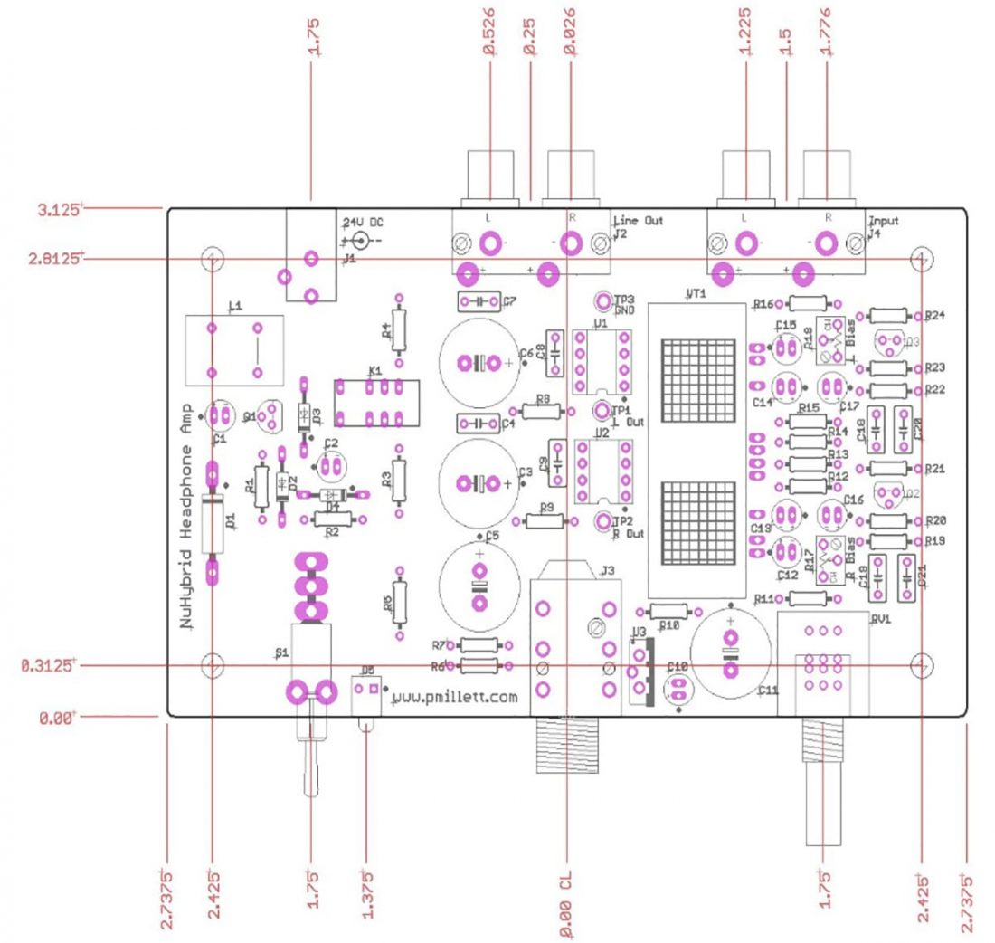
NuHybrid Circuit
The dimension of the NuHybrid PCB is 5.5” x 2.7”. Power input is 24V DC and current draw is approximately 80 mA.
The input signal comes from RCA jacks (located on the rear of the PCB) and travels through the volume pot. Because of the location of the volume pot in the circuit, the input impedance is equal to the impedance of the volume pot (the default value is 10K). The signal is capacitively coupled into a pair of emitter followers using 2N3094 NPN transistors.
The NuHybrid is Class A2, meaning that the control grid is biased slightly positive, so the grid draws a bit of current when driven. The output of the tube buffer is capacitor coupled using an 10uF capacitor in the Nutube grids. Positive grid bias of 0-3.3V is adjustable using trim pots. The 700 mV, 17mA per triode filament power and the positive grid bias comes from a 3.3V linear regulator.
The Nutube plates are coupled directly to a pair of OpAmp buffers (OPA551). The OpAmp output is capacitively coupled to the headphone jack through electrolytic capacitors (bypassed with small film caps).
Output RCA jacks are included for use as a preamp. The output RCA jacks are deactivated when a headphone plug is inserted in the jack. Both headphone and RCA outputs are muted for approximately 10 seconds upon start-up to eliminate any ‘thump’ noise from capacitor charging.
Assembling the NuHybrid
To populate the NuHybrid PCB, you will need a few basic tools:
- Soldering iron
- Solder – Tin/lead 63/37 is recommended. The PCB has a tin/lead hot air solder leveled (HASL) coating.
- Wire cutters
- Fine tipped needle nose pliers
- Tiny flathead screwdriver
- Digital Multimeter (DMM)
Experience is not necessary to populate the PCB, as this is designed to be a basic kit to assemble, however a little soldering practice would not hurt. With some care and careful following of instructions, this project is entirely appropriate for a first-time builder.
Assembly of the components on the PCB can happen in any order, however the instructions organize things to install the lowest profile components first and work up through the taller parts. Parts are numbered from the lower left corner when the PCB is positioned so that the writing is the proper orientation.
While the leads of components can be bent with your fingers, I find that more attractive results are obtained if I estimate the distance between mounting holes by eye, and then bend the leads to perfect 90 degree angles (using needle nose pliers) prior to insertion.
In general, to populate a PCB with components, each component is inserted in the board from the top through the appropriate holes. The component is pulled down to be flush with the top of the board and the leads (tinned metal wires extending from the component) are gently bent outwards on the back of the PCB to hold it in place. This temporarily holds the component in place, and readies it for soldering.
The soldering iron is momentarily touched to heat the solder pad on the board and the lead evenly and at the same time. Solder is applied to the hot pad and lead, which liquifies and creates a small, neat mound. If done properly, the solder cools to a cone shape and hardens to encompass the pad and hold the lead securely. The excess lead beyond the solder is then trimmed off using wire cutters.
This is just a quick overview of the soldering process, and there are many excellent in-depth tutorials available if you are new to soldering or want to learn more.
Repeat until all components are attached, triple-checking before applying solder for all components (capacitors and diodes) that have to be oriented properly for polarity.
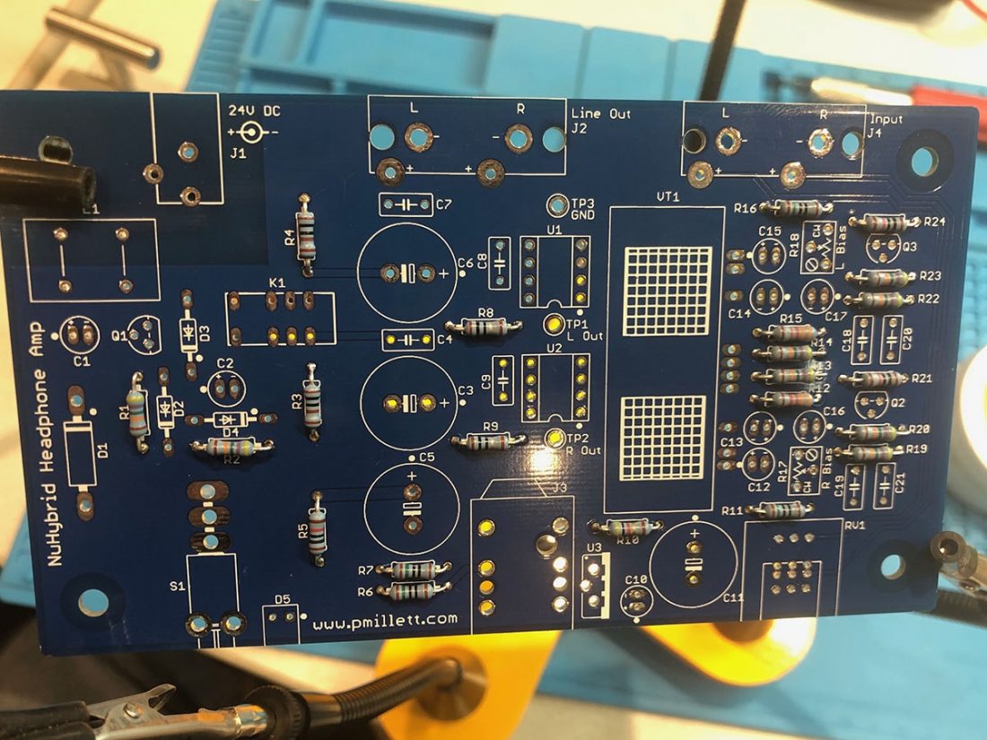
The instructions walk the builder through installing (in order):
- Resistors
- Diodes
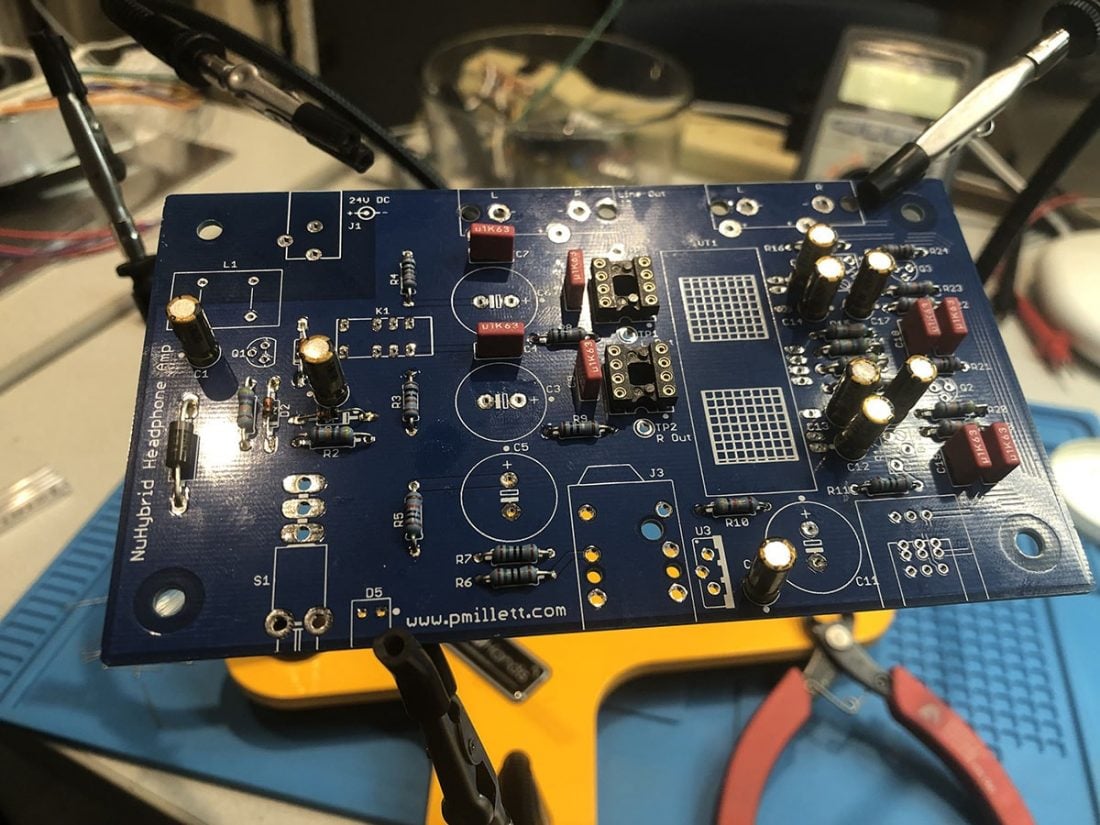
- IC Sockets (for holding OpAmps)
- Film Capacitors
- Electrolytic capacitors
- Bias Trim Pots
- Transistors
- Voltage Regulator
- Test Points
- Relay
- Inductor
- Volume Control
- Headphone Jack
- Power Switch
- Power Jack
- Input and Output RCA Jacks
- Power LED
- Nutube
- OpAmps
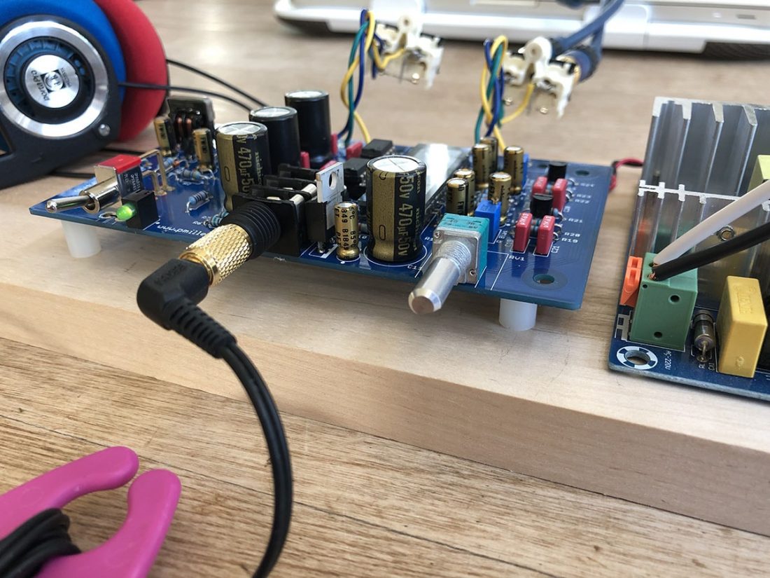
Power On Test
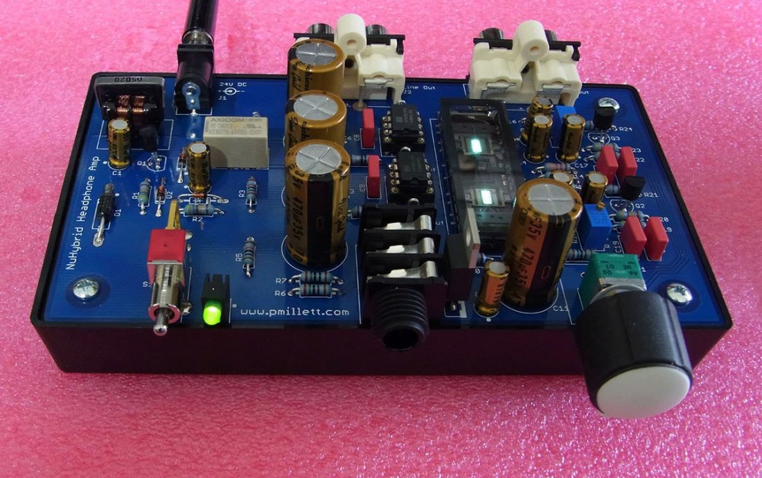
It may seem like a long assembly list, but populating the board is an easy to finish project in a single afternoon or evening (about 2-3 hours depending on the builder’s skill). Once the board is fully assembled, and DOUBLE-CHECKED AGAIN, it’s time to plug it in and flip the switch. The green power LED should immediately light up and the Nutube should start to glow bluish-white.
Using a Digital Multimeter (DMM) measure the DC voltage between the test points. The voltage should be adjusted to 11V using a tiny flathead screwdriver on the trim pots. The 11V is Pete’s recommended value, and any voltage setting you choose will not harm the amplifier, but will influence the sound.
Find your sacrificial…err, I mean… test headphones. Plug the headphones and a source in and give it a listen.
If there are any issues encountered, it’s almost certainly a problem with the soldering of one or more components. Since you carefully quadruple-checked the orientation and positioning of all components, an open joint or shorted leads are the most likely candidates. Almost all electronic troubleshooting recommends reflowing and redoing all solder joints carefully, one by one. Joints should look like tiny volcanoes, not blobs or balls.
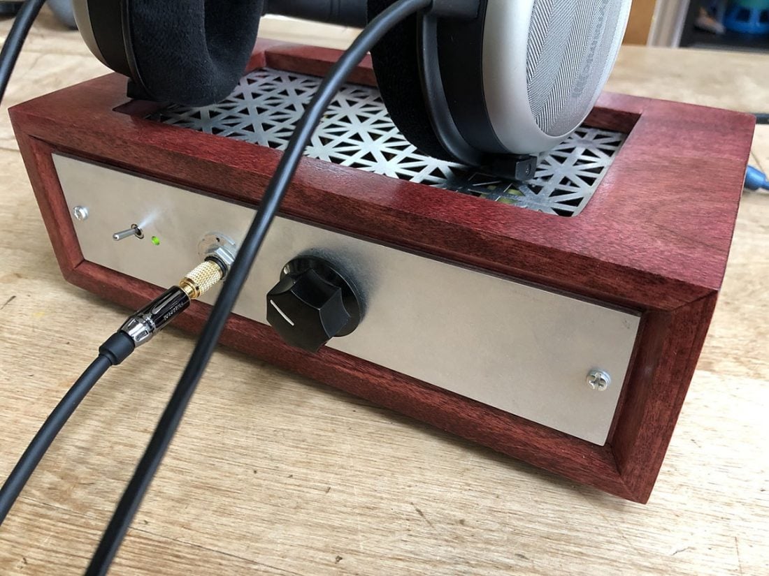
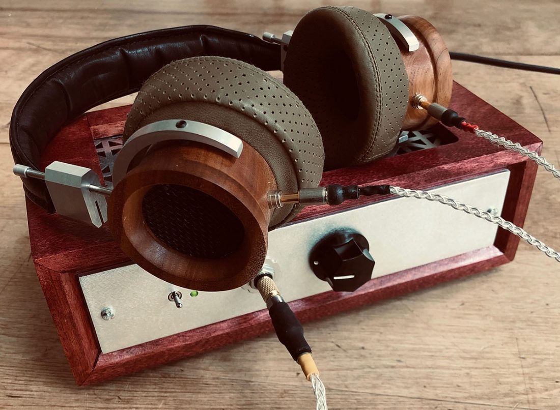
Making a Decorative Wood and Aluminum Case
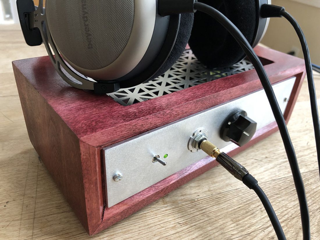
Pete’s BOM calls for mounting the amplifier as a bare board seated in a small, plastic half-case with no top, sides, front or back. Since all voltages used are low, there is no danger in using it this way and it does nicely show off the Nutube. However, if you’ve read any of my DIY School articles, it should come as no surprise that I would be building a more attractive enclosure for my NuHybrid.
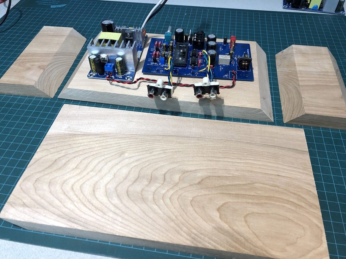
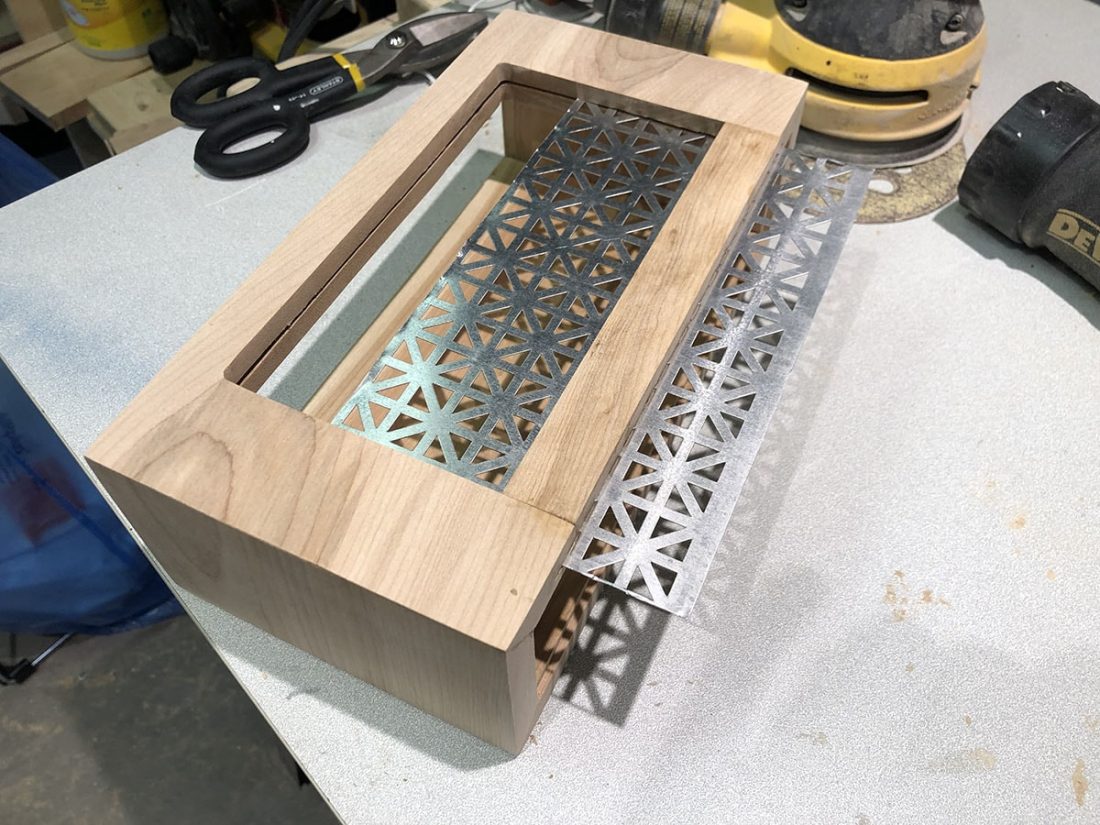
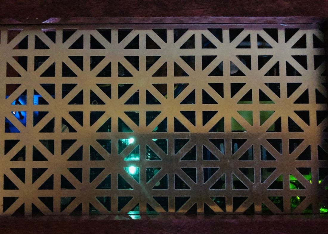
I ended up building a wooden case using birch hardwood cutoffs (less than $10) from my local hardware building supply store. While I was there, I found a sheet of metal grating in an attractive Union Jack pattern. (It was $20 but it is 2’x3’ and will serve for many future projects as well). Just what is needed to view the Nutube and to allow any heat to escape.
Front and back panels were manufactured from 2” wide x 1/8” thick aluminum stock from another hardware store $12).
Tools Used for the Case Build:
- Table saw
- Miter saw
- Band saw (for cutting the aluminum stock)
- Router table and various bits (including T-molding bit)
- Random orbit hand sander
- Drill and various bits
- Metal file
- Dremel
- Screwdrivers
- Tin snips
- Cabinet wood glue
- Sandpaper
- Hot glue
- Stain and polyurethane spray
Case Assembly
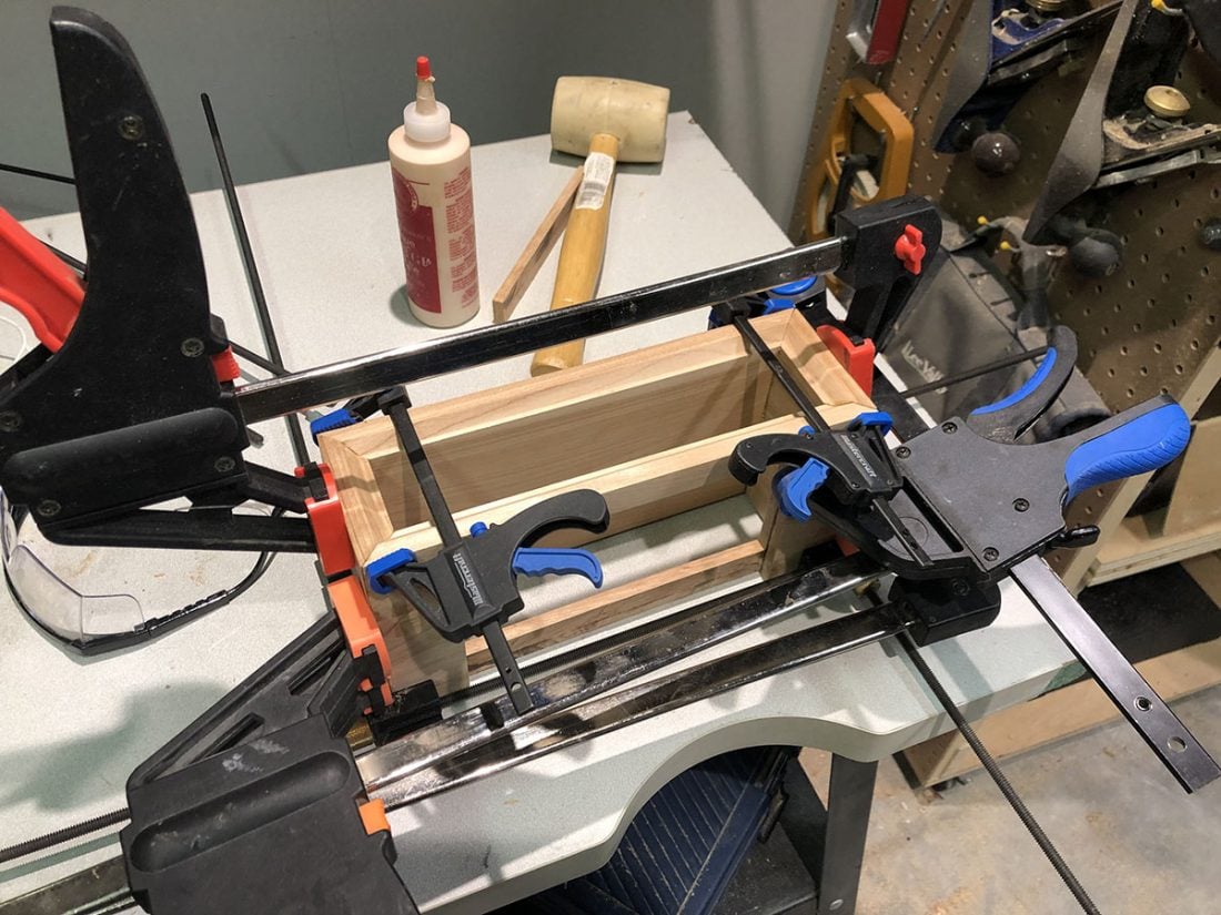
I used a table saw to cut the ½” birch to a uniform 5 ½” depth. I mitered each of the four pieces using my trusty old sliding compound miter saw to create a box (top, bottom and sides) 10 ½” wide x 3 ¼” high. The height was dictated by the aluminum stock width of 2”. Two small wooden pieces were added to the inner sides to give something for the front and rear aluminum plates to screw into. All the pieces were simply glued together using cabinet glue and clamped until they dried..
Using a small router table, I created the front profile and the rear slot to fit the aluminum plates. I also used the router to create the cutout for the top grate and the channel for the grate to slide into. I used a T-molding router bit to align a channel for the grate, centered in the wooden top piece.
After a disaster involving trying to do the top cutout in one piece, I settled for having to glue in a couple back pieces to hold the grate. This required, of course, completely having to make a new top piece since the first was wrecked spectacularly. Not my original intent, but it turned out fine.
Once I was happy with the fit and finish (take your time sanding, working up to 220 grit, it pays off in the end) I applied a few coats of burgundy stain. Finally 4 coats of gloss polyurethane was sprayed to seal and protect it. Although that may all sound like a complex process, just follow the directions on the cans. Wipe the stain on with a clean rag (I used blue paper shop towels) and once dry, rattle-can spray a few light coats of polyurethane; it is pretty hard to mess up.

Front and Rear Aluminum Plates
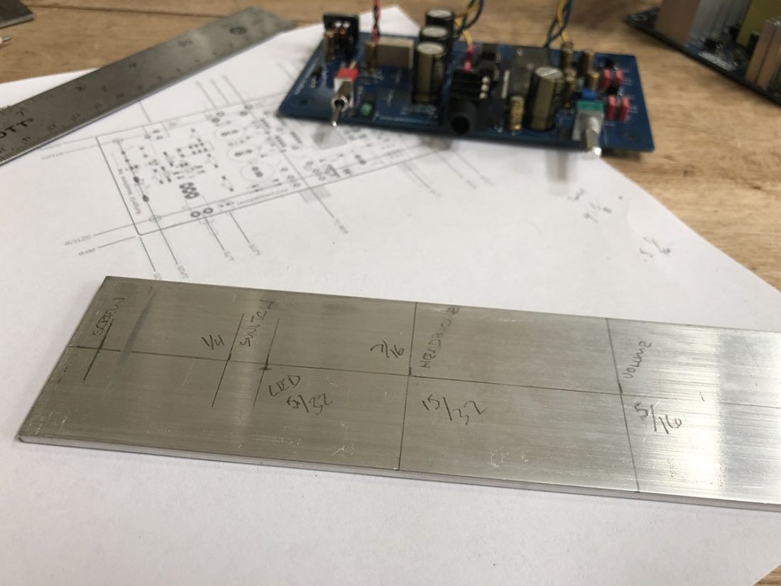
I centered the Nutube board vertically in the case and carefully measured and marked the front aluminum panel. Once marked, I center punched the holes and drilled the appropriate openings for screws, switch, power LED, headphone jack and the volume pot. I sanded the front and back surfaces of the panels to ensure that there were no stray metal shavings.
I found a very low-profile nut in my parts bin (from another potentiometer) that fit the thread pattern on the headphone jack. It would be very nice if the headphone jack came with a nut, but it does not. I used my scavenged nut to tighten the NuHybrid PCB to the front plate. A thin heatsink from a high intensity LED made a perfect decorative washer around the headphone jack under the nut.
I used plastic standoffs, from a TV wall-mount, under the NuHybrid board and (without the top grill in place) drilled pilot holes and screwed the PCB down into the bottom of the case. Since the NuHybrid is centered vertically on the front plate, it means there is almost ¾” of empty space underneath it. This space lead me to another upgrade that I’ll get to in the next section.
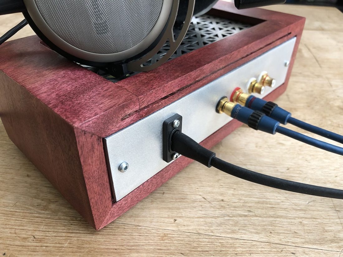
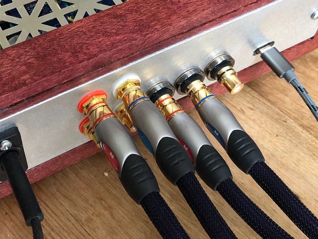
The power supply was mounted on shorter plastic standoffs immediately beside the NuHybrid board. Rather than installing the NuHybrid rear power input, I simply attached two wires directly to the power supply 24V output. In addition, I did not use, nor install the default RCA jacks on the NuHybrid board. Separate insulated RCA jacks were mounted to the rear aluminum plate, along with the power cord input for the power supply board.
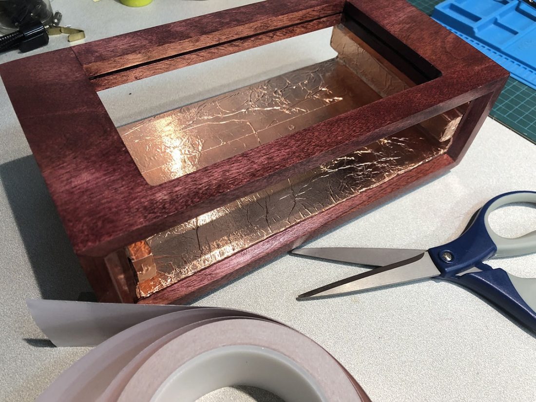
To finish up, I took everything out and completely covered the inside of the wooden case with conductive copper tapein an effort to minimize interference (EMI) and unwanted external noise from cell phones, wifi, etc. As it turned out, it is pretty much immune to cell phone noise – a big plus. Finally, the top grill was cut to fit using tin snips, slid into place from the back and secured semi-permanently with a couple dabs of hot glue in the rear slot.
Adding a DAC – The WesionTek Kahdas Tone Board
All that extra space behind and under the NuHybrid board got me to thinking about options. I’d recently read about this tiny and inexpensive DAC board that was measuring better than DACs at many times the price.
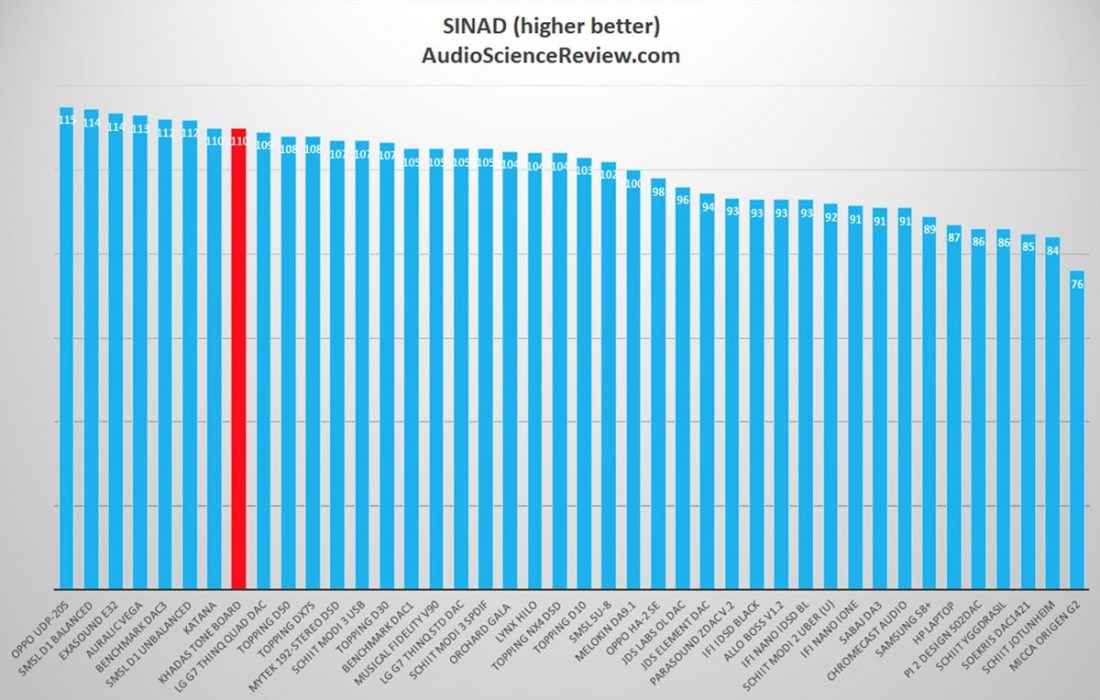
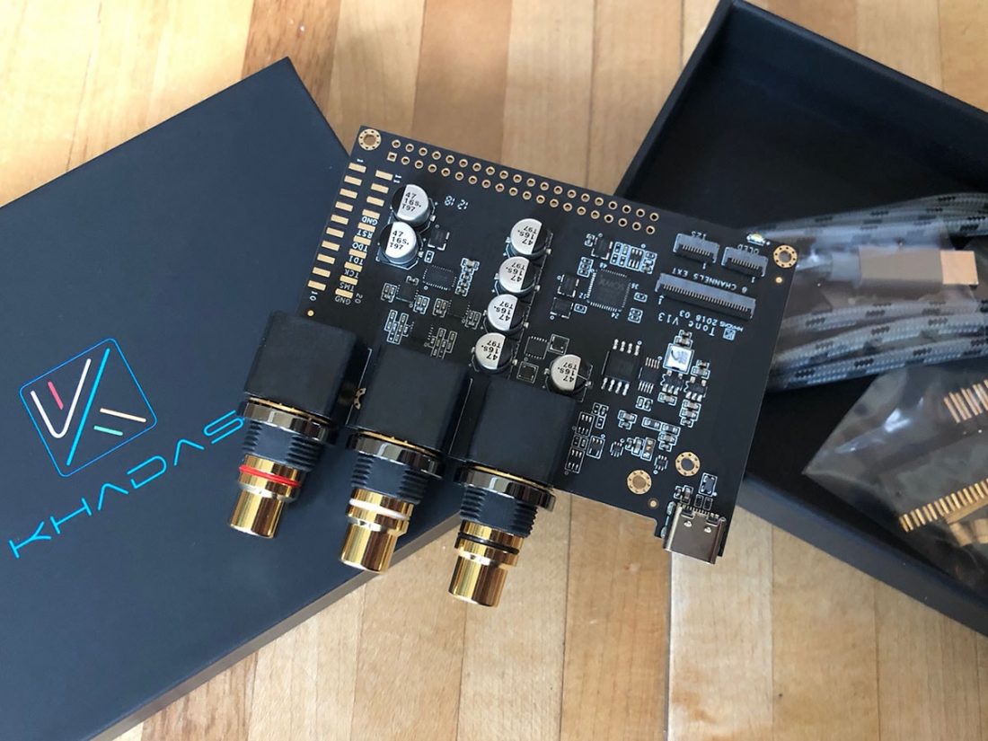
The Kahdas Tone Board is an odd duck; it is entirely without a case, as it was originally intended to be inserted directly on top of a tiny computer board. However, due to the outstanding sound quality measurement results, it has been quickly gathering popularity in the DIY community.
And (I rationalized to myself) wouldn’t it be nice to have all-in-one functionality in a single case that enclosed the DAC, amp and power supply?
Technical Specifications
- DAC: ES9038Q2M, 32 Bit Stereo
- THD+N: <= 0.000337% @ 1 KHz
- SNR: >= 120 dB @ 10 Hz – 20 KHz
- Sample Rate: PCM: 384 KHz @ 32 Bit, DSD: 256 @ 1 bit
- Jitter: Reference Clock: < 3 ps, Data Clock: < 30 ps
- Audio Formats: APE2/FLAC/OGG/WAV/ACC/ALAC/MP3/WMA
- USB-C Port: Power Supply(5V/500mA) & USB 2.0 Data
- S/PDIF: In: Up to 192KHz
- RCA: Stereo Output
- Dimensions: 82.0 x 74.5 x 17.0 mm
- Price: $100
Installing the Kahdas Tone Board
After taking a few measurements, I determined that the Tone Board would fit perfectly behind and a bit underneath the NuHybrid PCB. Of course this meant making another aluminum rear panel to fit. Holes had to be cut for the USB C input, digital input RCA jack, and two stereo output RCA jacks for the Tone Board. Tightening the nuts on the three threaded RCA jacks is more than sufficient to hold the Tone Board securely, so I did not attempt to attach it to the wooden case itself.
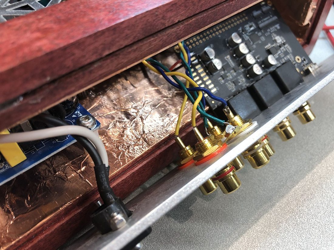
I used the fixed spacing of the Tone Board RCA jacks to orient and align the NuHybrid’s input and output jacks on the rear panel. It ended up all being a reasonably tight fit, nonetheless it all went in there so well, you’d swear it was the plan all along.
To finish it off, I soldered wires to a couple of unused 5V DC pads on the Tone Board PCB and installed a yellow LED on the front panel to the right of the volume control. I aligned and spaced it so it was an match to the NuHybrid power LED – which helped to visually balance the front panel.
Through some trial and error, I found the right combination of resistors (specifics will depend on what LED you choose) to sufficiently dim the yellow LED to match the green NuHybrid power LED. The yellow LED illuminates any time the Tone Board is plugged in via USB and receives power.
NuHybrid Upgrades
Pete recommends a few potential upgrade options when assembling the NuHybrid PCB:
Capacitors
The default capacitors are all high quality Nichicon Fine Gold audio electrolytic capacitors and Wima polyethylene film caps. The electrolytic capacitors in the positions C3 and C6 are directly in the audio signal (as well as the input coupling film caps in C20 and C21), so these are the most likely candidates for upgrade if desired.
It may be difficult to find better capacitors that will fit on the PCB, but depending on if you mount the NuHybrid in a custom case, it may be possible to mount components to the bottom of the board.
For a more detailed discussion of the variety of capacitors available, check out the Head-Fi thread.
OpAmps
As with most OpAmp rolling, there are many available options (and opinions on them) to replace the OPA551. The OpAmp must support a 24V power supply, 8 port socket and be unity gain stable.
Head-Fi builders report success with the boutique SparkOS Labs singles and Burson OpAmps. Other compatible options should include: AD797, AD825, AD8065, ADA4610, NE5534, OPA134, OPA604, or OPA627.
Power Supply
A linear power supply can be used in place of the suggested switching power supply, “…assuming it has reasonable filtering and/or is regulated so that it doesn’t have a lot of 120Hz output ripple. 120Hz ripple will probably cause more audible artifacts than the switching regulator ripple.” – Pete Millett on Head-Fi
RCA Connectors
The stock RCA jacks are basic non-gold plated versions. Off board mounting (like I did) will require separate insulated connectors. There are lots of options, but I went with basic gold plated jacks.
Transistors
It is possible to swap in a JFET (2SK170 or LSK170) in place of the 2N3904 transistors, however a gate stopper resistor (1K in series with the gate terminal) is needed to prevent oscillation.
Volume Control Potentiometer
I used the stock BOM pot in my own build and I agree with his assessment. It is indeed noisy (crackling sounds) and somewhat unbalanced (left channel louder) at the very lowest settings, but this is below any usable listening level for me, so has minimal impact in practice.
If you are willing to pay the price for an upgrade, Pete did design the board to also accept a couple common high-quality potentiometers, the Alps Blue Velvet ($20) or the TKD 2CP-601 ($40). The original is a 10k pot, selected because there should be less noise pickup with a lower input resistance, but Pete states that replacing it with 50k or 100k is fine.
NuHybrid Performance and Measurements
My personal NuHybrid build follows the BOM with the small differences of power supply, RCA jacks, case, and volume knob. None of these changes should dramatically impact the sound quality from the standard build and as such, this performance discussion should be applicable to anyone building a stock NuHybrid.
Power
The gain is unmodified from the Nutube stage (about 6x), which proves to be a bit too much for sensitive IEMs. Paired with the KZ ZS10 Pro (24 Ohm, 111 dB) there is audible hiss with the volume control turned all the way down. In this position the music also audibly bleeds through. As a result, I do not recommend the stock NuHybrid for pairing with highly efficient IEMs.
The drive capability is limited by the output buffer. Pete rates the power output of the stock NuHybrid as approximately 6.5V RMS into 30 or 150 ohms, or 1.3 watts into 30 ohms.
Using the OPA551, the NuHybrid is more than powerful enough to easily drive any of my full sized headphones from the efficient Meze 99 Classics (32 Ohm, 103 dB), all the way up to the power intensive Beyerdynamic T1 (600 Ohm, 104 dB). The T1 can get to louder than comfortable listening volume at approximately ½ on the NuHybrid’s volume control. That means it has plenty of power on hand for any of my full-sized headphone needs.
Frequency Response
The frequency response is impressively flat and with less than 1dB of mismatch between the two halves of the Nutube, which is better matching than the volume control. Pete describes the overall frequency response of the NuHybrid as:
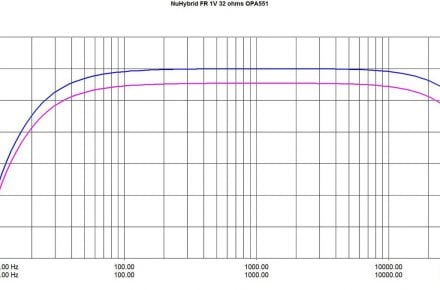
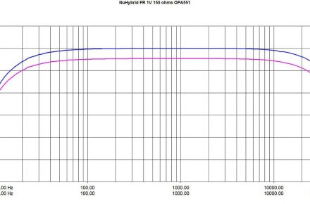
In personal listening, the above seems accurate. The amplifier appears to have no issues reproducing either end of the audible spectrum, with no audible bumps or dropouts with any frequencies. Overall, it’s a remarkably pleasant and even sounding amplifier.
Harmonics
Tube amps are not theoretical “ideal” amplifiers that simply apply voltage gain. With a tube amplifier, it is important to understand that harmonic distortion is part of the intended sound signature. Harmonic distortion may be defined as the presence of frequencies in the output signal that are not present in the input signal. These frequencies may be even or odd.
Harmonics may be seen at 2nd, 3rd, 4th, etc levels. Higher-order harmonics tend to be more audible (and thus less desirable) because they are further from the original frequency. 7th order harmonics and above are considered very undesirable as they tend to be harsh sounding.
Even harmonics are typically considered more pleasant-sounding than odd harmonics. The desirability of low-level, even harmonics is why 2nd order harmonics are often touted as “what you want” with a tube amplifier.
Of course, personal preference and the music listened to, may lead one to prefer the sweet, tube-like characteristics of even harmonics, or the more-detailed, brighter sound of odd harmonics. Lower-order harmonics tend to mask higher-order harmonics, but higher-order harmonics tends to be more audible, and as we noted above, less pleasant sounding.
So a typical “good sounding” tube amp will try to minimize total distortion, and make sure the higher-level harmonics are at a smaller amplitude than lower-level harmonics (typically in a stair-step pattern downwards).
Harmonics are measured using a Fast Fourier Transform (FFT) graph which displays a signal both in the time domain and the frequency domain. The harmonics of a signal’s frequency appear at higher frequencies than fundamental frequency on the FFT graph.
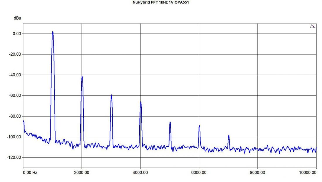
The NuHybrid output displays traditional single-ended triode amplifier characteristics with strong 2nd order harmonics and subsequently smaller higher-level harmonics. As we discussed above, these measurements are consistent with that “tube sound” that some folks (such as myself) enjoy.
The bias pots can be adjusted to change or tune the harmonics as desired. Setting the bias voltage slightly lower (8-9 V rather than 11 V) will introduce more 2nd order harmonics, which tends to smooth any harsh higher frequencies. For all my listening and observations, I stuck with the recommended 11 V.
The NuHybrid is not designed to be a minimal THD amplifier. At 1V RMS, THD is approximately 0.6%. Clipping (5% THD) occurs at 6V.
Sound Quality
The NuHybrid conveys the impression of exceptional detail and transparency, with the expected warm harmonics of tube amplification. The sound is smooth across the entire audible spectrum and manages to sound lush and fun. It may not be to your tastes, but for a tube amp fan like myself, the NuHybrid does not disappoint.
The NuHybrid presents a quiet background with most anything but the most sensitive of headphones. However, keep in mind that it is not designed to be a very low distortion amplifier. It performs much as you would expect a traditional single-ended triode tube amp to perform, with audible 2nd order harmonics.
Drawbacks
While the Nutube adds great flavor to the sound, NuHybrid isn’t without the compromises inherent to the choice of using the Nutube 6P1 in the circuit. It does exhibit noticeable ringing when powered on (for about 10 seconds) following the muting circuit engaging.
The sound is audible through all the headphones I tried (but reduced with less sensitive headphones) before slowly fading away. Moving the case, or even just adjusting the volume control causes slight ringing microphonics as well. If you are a frequent volume adjuster, or sensitive to the tube ringing sound, the NuHybrid may not be for you.
Unfortunately, this ringing is just the normal microphonic behavior of the Nutube and not something that can be ‘fixed’. Pete originally thought the power on ‘ping’ was due to the activation of the muting relay, but later amended this to be caused by the flipping of the power switch, which has a firm ‘click’ when engaged.
Conclusion
I am extremely satisfied with how this project turned out. The NuHybrid amplifier sounds great, albeit with the caveat of having too much gain to pair well with highly efficient IEMs. It has power to spare for demanding headphones such as the Beyerdynamic T1 and Fostex T50RP mk3. Regardless of the unique design of the Nutube, it produces a traditional tube sound, just housed in a brand new shape.
Of course, that pleasing tube sound comes with a significant compromise, which may be a deal breaker for some. While the NuHybrid’s ringing sound is very similar in timbre to traditional tube ringing, the Nutube is far more microphonic than any conventional tube I’ve ever encountered. I’m used to having to strike or tap a tube amplifier to elicit a pinging noise. However with the NuHybrid, flicking the power switch, or even adjusting the volume, will set the tube ringing.
If you can live with, and perhaps embrace these characteristics (as I have), the NuHybrid is a terrific sounding, powerful, and unique tube amplifier. Tube amplification is subjective; tubes will never objectively measure perfectly. Distortion and harmonics are part of the charm. But if tube sound appeals to you, the NuHybrid doesn’t disappoint. I highly recommend the NuHybrid to anyone interested in DIY, tube amplification, or simply for anyone who desires an excellent sounding desktop headphone amp with plenty of power for full sized headphones.
If I may make a recommendation, I feel the quality of the NuHybrid kit warrants a better case than the open-board design from the BOM. You don’t have to go all out in creating a case from scratch, as there is a readily available 3D printed option. In addition, there are many interesting alternative case ideas in the Head-Fi thread.
Also worth noting, if you are in the market for a new DAC, the Kahdas Tone Board really is deserving of consideration. This surprisingly well-made device is performing well beyond its modest price point. While it certainly doesn’t need to be included in the same enclosure as the NuHybrid, its tiny size makes the Tone Board a tempting addition to any DIY project.
As with all DIY projects, you gain the personal satisfaction of creating something exclusive and ending up with something exactly how you want it. It’s just that much simpler when you pick a project like the NuHybrid that has excellent support, detailed instructions, a comprehensive BOM, and an active forum for discussion or questions. It makes it so easy!
Great write-up and explanation!
This is indeed another great write up – this build is on my list, PCB and tube ordered from Pete.
You say that you didn’t connect the Khadas Tone Board internally so you would be able to use it with other amps. Just curious, what DAC were you using previously?
Enjoyed the write-up as well as your other articles on DACs.
Thanks.